AND Gate
Overview
- Purpose: The AND gate performs a logical AND operation on its inputs. The output is HIGH (logical '1') only when all inputs are HIGH. If any input is LOW (logical '0'), the output is LOW.
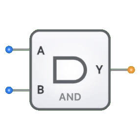
- Symbol: The AND gate is represented by a D-shaped symbol with a flat input side and a curved output side.
- DigiSim.io Role: Serves as a fundamental building block in digital logic circuits, implementing the Boolean AND operation.
Functional Description
Logic Behavior
The AND gate implements logical conjunction, producing a HIGH output only when all inputs are HIGH.
Truth Table (for a 2-input AND gate):
| Input A | Input B | Output Y |
|---|---|---|
| 0 | 0 | 0 |
| 0 | 1 | 0 |
| 1 | 0 | 0 |
| 1 | 1 | 1 |
Boolean Expression: Y = A · B (Y equals A AND B)
Inputs and Outputs
- Inputs: The AND gate has 2 inputs (A, B).
- Output: A single 1-bit output representing the result of the AND operation.
Visual Representation in DigiSim.io
The AND gate is displayed with input pins on the left side and an output pin on the right side. The gate uses the standard D-shaped symbol with a curved right side. When connected in a circuit, the component visually indicates the logic state of its pins through color changes on connecting wires.
Educational Value
Key Concepts
- Boolean Algebra: Reinforces the concept of the logical AND operator in Boolean expressions.
- Combinational Logic: Demonstrates a fundamental combinational logic circuit where the output depends solely on the current input values.
- Truth Tables: Helps understand how to read and interpret logic gate behavior through truth tables.
- Logical Conjunction: Illustrates the concept of logical conjunction in propositional logic.
Learning Objectives
- Understand the logical AND operation and its truth table representation.
- Learn how AND gates serve as building blocks for more complex digital circuits.
- Recognize standard symbol conventions for logic gates in digital electronics.
- Apply the AND operation to solve real-world logic problems.
- Identify the relationship between the AND function and its implementation in hardware.
Usage Examples/Scenarios
- Condition Verification: Used to verify that multiple conditions are simultaneously true before proceeding with an action.
- Data Validation: In computer systems, AND gates ensure all criteria are met before an operation is performed.
- Gating Control: Controls the passage of a signal based on an enable signal (one input is data, the other is control).
- Bit Masking: Extracting specific bits from a binary number by ANDing with a mask.
- Security Systems: Ensuring multiple safety conditions are met before granting access.
Technical Notes
- AND gates can be implemented using various technologies, including transistor-transistor logic (TTL) and complementary metal-oxide-semiconductor (CMOS).
- The propagation delay of an AND gate depends on the technology used and increases slightly with the number of inputs.
- Multiple AND gates can be combined with other logic gates to create complex logical functions.
- In digital circuit design, AND gates are often used in conjunction with OR and NOT gates to implement any Boolean function.
- In DigiSim.io, the AND gate's behavior simulates real-world digital components, including proper handling of undefined inputs.