4-bit Adder
Overview
- Purpose: The 4-bit Adder is a digital circuit that performs binary addition on two 4-bit numbers. It accepts two 4-bit inputs (A and B), along with an optional carry-in bit (Cin), and produces a 4-bit sum output (S) and a carry-out bit (Cout).
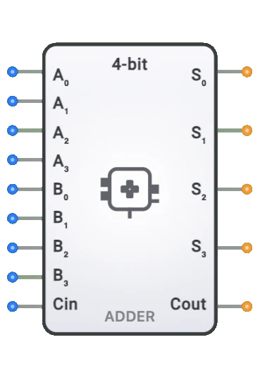
- Symbol: The 4-bit Adder is represented by a rectangular block with inputs for the two 4-bit operands (A[3:0] and B[3:0]) and carry-in (Cin) on the left side, and outputs for the 4-bit sum (S[3:0]) and carry-out (Cout) on the right side.
- DigiSim.io Role: Serves as a fundamental building block in arithmetic logic units (ALUs), forming the basis for implementing various arithmetic operations in digital systems including processors, calculators, and control units.
Functional Description
Logic Behavior
The 4-bit Adder performs binary addition according to the equation: A + B + Cin = (Cout, S). Each bit position adds the corresponding bits from A and B along with the carry from the previous position.
Truth Table (Sample Entries - Due to large number of combinations):
| A[3:0] | B[3:0] | Cin | S[3:0] | Cout | Note |
|---|---|---|---|---|---|
| 0000 (0) | 0000 (0) | 0 | 0000 (0) | 0 | Zero addition |
| 0001 (1) | 0001 (1) | 0 | 0010 (2) | 0 | Simple addition |
| 1111 (15) | 0001 (1) | 0 | 0000 (0) | 1 | Overflow to 16 |
| 1010 (10) | 0101 (5) | 0 | 1111 (15) | 0 | Sum within range |
| 1111 (15) | 1111 (15) | 0 | 1110 (14) | 1 | Maximum + maximum |
Inputs and Outputs
Inputs:
- A[3:0]: 4-bit first operand.
- B[3:0]: 4-bit second operand.
- Cin: 1-bit carry input for cascading with other adders or for incrementation.
Outputs:
- S[3:0]: 4-bit sum result.
- Cout: 1-bit carry output indicating overflow beyond 4 bits.
Configurable Parameters
- Propagation Delay: The time it takes for outputs to change after input changes, configurable in DigiSim.io simulation settings.
- Implementation Method: Some versions may allow selection between different internal implementations (ripple carry, carry lookahead, etc.) affecting speed and resource usage.
Visual Representation in DigiSim.io
The 4-bit Adder is displayed as a rectangular block with clearly labeled inputs on the left side (A[3:0], B[3:0], Cin) and outputs on the right side (S[3:0], Cout). When connected in a circuit, the component visually indicates the current values on its inputs and outputs through the color coding of wires, allowing users to track the flow of binary data through the system.
Educational Value
Key Concepts
- Binary Addition: Demonstrates how computers perform addition on binary numbers.
- Carry Propagation: Illustrates how carries flow from less significant to more significant bits.
- Digital Arithmetic: Shows the fundamental building block for computer arithmetic operations.
- Overflow Detection: Introduces the concept of detecting when a result exceeds the available bit width.
- Modular Design: Exemplifies how complex operations can be built from simpler components.
Learning Objectives
- Understand binary addition and how it's implemented in digital circuits.
- Learn how carry propagation affects the performance of digital adders.
- Recognize different adder implementations and their trade-offs.
- Apply 4-bit adders in designing arithmetic circuits and simple processors.
- Comprehend how overflow is detected and handled in fixed-width arithmetic.
Usage Examples/Scenarios
- Arithmetic Logic Units (ALUs): Core component for CPU arithmetic operations and address calculations.
- Binary Counters: Creating synchronous counters with specific counting sequences.
- Digital Signal Processing: Sample value calculations and signal amplitude operations.
- Memory Address Generation: Calculating offsets and addresses in memory systems.
- Small-Scale Computational Circuits: Building block for implementing calculators and small processors.
- Program Counter: Incrementing the program counter in a simple CPU design.
Technical Notes
- The 4-bit adder can be implemented using various architectures that trade off between speed and complexity:
- Ripple Carry Adder: Simplest implementation but has linear delay with bit width.
- Carry Lookahead Adder: Faster operation with logarithmic delay but more complex circuitry.
- Carry Select Adder: Good compromise between speed and resources.
- For signed arithmetic, the carry-out does not correctly indicate overflow; instead, overflow occurs when the sign of the result differs unexpectedly from the operands.
- Multiple 4-bit adders can be cascaded to perform addition on wider data (8-bit, 16-bit, etc.) by connecting the carry-out of one adder to the carry-in of the next.
- In DigiSim.io, the adder's propagation delay simulates real-world behavior, with the worst-case delay occurring when a carry must propagate from the least significant bit to the most significant bit.
Characteristics
- Bit Width:
- 4-bit operation (can be extended for wider operations)
- Propagation Delay:
- Ripple carry: O(n) delay where n is the number of bits
- Approximately 4 times the delay of a single full adder
- Number Range:
- Can add values from 0 to 15 (without carry-in)
- With carry-in, can handle values up to 16
- Output Range:
- Sum outputs represent values from 0 to 15
- Carry output indicates when result exceeds 15
- Power Consumption:
- Moderate, depends on implementation technology
- Proportional to switching activity during addition
- Circuit Complexity:
- Medium (requires 4 full adders)
- Each full adder requires 2 half adders and an OR gate
- Speed:
- Limited by carry propagation
- Carry must ripple through all stages in worst case
- Hardware Cost:
- Approximately 4 times the cost of a single full adder
- Typically around 20-28 logic gates in total
Implementation Methods
- Ripple Carry Adder
- The simplest implementation using four full adders in cascade
- Carry propagates from least significant bit to most significant bit
graph LR
    A0[A0] --> FA0[Full Adder 0]
    B0[B0] --> FA0
    CIN[Carry In] --> FA0
    FA0 -->|S0| S0[Sum 0]
    FA0 -->|C0| FA1[Full Adder 1]

    A1[A1] --> FA1
    B1[B1] --> FA1
    FA1 -->|S1| S1[Sum 1]
    FA1 -->|C1| FA2[Full Adder 2]

    A2[A2] --> FA2
    B2[B2] --> FA2
    FA2 -->|S2| S2[Sum 2]
    FA2 -->|C2| FA3[Full Adder 3]

    A3[A3] --> FA3
    B3[B3] --> FA3
    FA3 -->|S3| S3[Sum 3]
    FA3 -->|COUT| COUT[Carry Out]
Operation: Carry ripples through each stage sequentially, LSB to MSB.
Carry Look-ahead Implementation
- Faster implementation that computes carries in parallel
- Uses generate (G) and propagate (P) signals to predict carries
- Reduces worst-case delay from O(n) to O(log n)
Integrated Circuits
- Available in 74xx series logic families (e.g., 74LS283)
- Dedicated 4-bit adder chips with optimized internal structure
FPGA/ASIC Implementation
- Custom implementations using hardware description languages
- Can be optimized for specific performance/area trade-offs
Applications
Arithmetic Logic Units (ALUs)
- Core component for performing arithmetic operations
- Used in conjunction with other circuits for subtraction, comparison, etc.
Microprocessor Design
- Fundamental part of CPU arithmetic units
- Used in address calculation and data manipulation
Digital Signal Processing
- Signal amplitude addition and mixing
- Filter coefficient calculations
Digital Counters
- Used to increment counter values
- Address generation in memory systems
Binary Calculators
- Basic addition operations
- Foundation for more complex calculations
Error Correction Circuits
- Checksum calculation
- CRC (Cyclic Redundancy Check) implementations
Digital Control Systems
- Processing sensor inputs and calculating control outputs
- PID controller implementations
Limitations
Speed Limitation in Ripple Carry Implementation
- Carries must propagate sequentially through each bit position
- Worst-case delay is proportional to the number of bits
Overflow Detection
- Standard implementation does not detect overflow conditions
- Additional logic needed to detect when result is out of range
Limited Bit Width
- Restricted to 4-bit operands
- Multiple units needed for wider operations
No Subtraction Capability
- Performs addition only
- Requires additional logic for subtraction (e.g., two's complement)
Power Consumption
- Multiple transitions during carry propagation
- Can be a concern in battery-powered applications
Circuit Implementation Detail
Full Adder Implementation
Each of the four full adders in a 4-bit ripple carry adder computes:
Si = Ai ⊕ Bi ⊕ Ci
Ci+1 = (Ai · Bi) + (Ai · Ci) + (Bi · Ci)
Where:
- Si is the sum bit
- Ci is the carry-in
- Ci+1 is the carry-out
Carry Look-ahead Implementation
The carry look-ahead adder uses:
Generate: Gi = Ai · Bi
Propagate: Pi = Ai ⊕ Bi

C1 = G0 + (P0 · CIN)
C2 = G1 + (P1 · G0) + (P1 · P0 · CIN)
C3 = G2 + (P2 · G1) + (P2 · P1 · G0) + (P2 · P1 · P0 · CIN)
COUT = G3 + (P3 · G2) + (P3 · P2 · G1) + (P3 · P2 · P1 · G0) + (P3 · P2 · P1 · P0 · CIN)

Si = Pi ⊕ Ci
Related Components
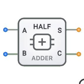
- Half Adder: The basic building block for single-bit addition without carry-in
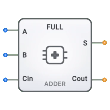
- Full Adder: The fundamental component for single-bit addition with carry-in
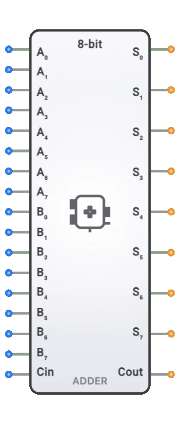
- 8-bit Adder: Extended version of the 4-bit adder for wider operands
- Subtractor: Circuit that performs binary subtraction, often implemented using adders
- ALU: Comprehensive circuit that incorporates adders along with other arithmetic and logic functions
- BCD Adder: Special adder for decimal (BCD) numbers
- Carry Look-ahead Generator: Accelerates addition by computing carries in parallel
- Adder-Subtractor: Combined circuit that can perform both addition and subtraction