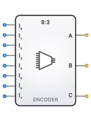
8-to-3 Encoder
Overview
- Purpose: The 8-to-3 Encoder is a digital combinational circuit that converts eight mutually exclusive input lines into a 3-bit binary code, representing which of the input lines is active.
- Symbol: Typically represented as a rectangular block with eight inputs (I0-I7) and three outputs (Y2, Y1, Y0).
- DigiSim.io Role: Serves as an essential data reduction component, enabling the conversion of one-hot signals to compact binary representations for more efficient processing and transmission.
Functional Description
Logic Behavior
The 8-to-3 Encoder detects which of its eight input lines is active and produces a unique 3-bit binary code that corresponds to the active input. In a standard encoder, only one input should be active at any time.
Truth Table:
| Inputs | Outputs | |||||||||
|---|---|---|---|---|---|---|---|---|---|---|
| I7 | I6 | I5 | I4 | I3 | I2 | I1 | I0 | Y2 | Y1 | Y0 |
| 0 | 0 | 0 | 0 | 0 | 0 | 0 | 1 | 0 | 0 | 0 |
| 0 | 0 | 0 | 0 | 0 | 0 | 1 | 0 | 0 | 0 | 1 |
| 0 | 0 | 0 | 0 | 0 | 1 | 0 | 0 | 0 | 1 | 0 |
| 0 | 0 | 0 | 0 | 1 | 0 | 0 | 0 | 0 | 1 | 1 |
| 0 | 0 | 0 | 1 | 0 | 0 | 0 | 0 | 1 | 0 | 0 |
| 0 | 0 | 1 | 0 | 0 | 0 | 0 | 0 | 1 | 0 | 1 |
| 0 | 1 | 0 | 0 | 0 | 0 | 0 | 0 | 1 | 1 | 0 |
| 1 | 0 | 0 | 0 | 0 | 0 | 0 | 0 | 1 | 1 | 1 |
Note: Only one input should be active (high) at a time. Multiple active inputs or all inactive inputs represent invalid conditions in a basic encoder.
Inputs and Outputs
Inputs:
- I0-I7: Eight 1-bit inputs, where typically only one is active at a time in standard encoders.
Outputs:
- Y2: Most Significant Bit (MSB) of the 3-bit output code.
- Y1: Middle bit of the 3-bit output code.
- Y0: Least Significant Bit (LSB) of the 3-bit output code.
Configurable Parameters
- Input Activation Level: Whether inputs are active-high or active-low.
- Output Logic: Whether outputs follow positive or negative logic.
- Priority Encoding: Whether the encoder has priority logic to handle multiple active inputs.
- Valid Output Signal: Whether the encoder produces a signal indicating a valid input condition.
- Propagation Delay: The time it takes for outputs to change after an input change.
Visual Representation in DigiSim.io
The 8-to-3 Encoder is displayed as a rectangular block with eight input pins on the left side (I0-I7) and three output pins (Y2, Y1, Y0) on the right side. When connected in a circuit, the component visually indicates the active input and corresponding binary output through color changes on connecting wires.
Educational Value
Key Concepts
- Binary Encoding: Demonstrates how multiple signal lines can be encoded into a more compact binary representation.
- Data Reduction: Shows how to reduce the number of signal lines needed to represent information.
- Code Conversion: Illustrates the conversion from one-hot (unary) code to binary code.
- Combinational Logic: Presents a practical application of OR gates in a useful digital function.
- Signal Multiplexing: Introduces concepts related to signal selection and channel identification.
Learning Objectives
- Understand how digital systems efficiently encode multiple signals into binary form.
- Learn the relationship between input activation and corresponding binary output codes.
- Recognize the challenges of invalid input conditions and how they might be handled.
- Apply encoding concepts to design systems with reduced wiring and simplified data paths.
- Comprehend the logical duality between encoders and decoders in digital systems.
Usage Examples/Scenarios
- Keyboard Encoding: Converting multiple key inputs into binary codes for processing.
- Priority Interrupt Handling: Encoding multiple interrupt sources into a binary vector for a processor.
- Sensor Input Processing: Converting multiple sensor activations into compact binary data.
- Memory Bank Selection: Encoding which memory bank is currently active or being addressed.
- Input Device Selection: Generating binary codes that identify which input device is active.
- State Encoding: Converting state signals in state machines to compact binary representation.
- Multiplexer Control: Generating select signals for controlling multiplexers from individual control lines.
Technical Notes
- The 8-to-3 encoder implements the following boolean expressions: Y0 = I1+I3+I5+I7, Y1 = I2+I3+I6+I7, Y2 = I4+I5+I6+I7.
- Basic encoders do not handle multiple active inputs well; priority encoders are needed for such cases.
- The input I0 activation cannot be distinguished from the all-inputs-inactive state without additional logic.
- Some encoder implementations include a "valid" output that indicates when at least one input is active.
- Encoders with priority logic will output the binary code corresponding to the highest-numbered active input.
- In DigiSim.io, the encoder behavior models standard encoder functionality with proper output generation for active inputs.
Characteristics
- Input Configuration:
- Eight inputs (I0-I7), where normally only one is active at a time
- Active-high inputs (1 represents an active input)
- Output Configuration:
- Three outputs (Y2, Y1, Y0) representing the 3-bit binary code
- Y2 is the Most Significant Bit (MSB)
- Y0 is the Least Significant Bit (LSB)
- Functionality:
- Converts a one-hot input (single active line) to binary
- Reduces eight signal lines to three binary lines
- Propagation Delay:
- Typically 5-15ns (technology dependent)
- Generally less than decoders of similar size
- Fan-Out:
- Each output typically drives 10-50 gates (technology dependent)
- Logic Levels:
- Compatible with standard logic families (TTL, CMOS)
- Circuit Complexity:
- Medium (requires multiple OR gates)
- Less complex than equivalent decoder circuits
- Limitations:
- Basic encoders have invalid states (multiple active inputs)
- No handling for all-zero inputs in simple implementations
Implementation Methods
- Using OR Gates
- Each output bit is formed by ORing specific inputs
- The boolean expressions for each output:
- Y0 = I1 + I3 + I5 + I7
- Y1 = I2 + I3 + I6 + I7
- Y2 = I4 + I5 + I6 + I7
graph LR
    I1[I1] --> OR0[OR Gate]
    I3[I3] --> OR0
    I5[I5] --> OR0
    I7[I7] --> OR0
    OR0 --> Y0[Y0 LSB]

    I2[I2] --> OR1[OR Gate]
    I3 --> OR1
    I6[I6] --> OR1
    I7 --> OR1
    OR1 --> Y1[Y1]

    I4[I4] --> OR2[OR Gate]
    I5 --> OR2
    I6 --> OR2
    I7 --> OR2
    OR2 --> Y2[Y2 MSB]
Encoding Pattern: Each output bit is HIGH when any input with that bit position set is active.
Priority Encoder Implementation
- Handles cases where multiple inputs are active
- Outputs the code for the highest-priority active input
- Uses additional priority logic and enables
Using Multiplexers
- Can be implemented with multiplexers and fixed inputs
- Less common but useful in specific FPGA architectures
Integrated Circuits
- Available in 74xx series logic families (e.g., 74148)
- Often implemented with priority encoding capabilities
- Some versions include enable inputs and valid output flags
Applications
Address Encoding
- Converting multiple select lines to binary addresses
- Memory bank selection encoding
- Register selection in processors
Input Processing
- Converting multiple sensor inputs to binary values
- Keyboard encoding in computer systems
- User input selection encoding
Multiplexer Control
- Generating select signals for larger multiplexer systems
- Channel selection in communication systems
- Input source selection in digital systems
Interrupt Processing
- Encoding multiple interrupt sources into binary values
- Priority interrupt handling in processor systems
- Device identification in multi-device systems
Data Compression
- Basic form of data encoding to reduce signal lines
- Converting one-hot codes to binary representation
- Part of larger encoding schemes in communication systems
Digital Instrumentation
- Converting multiple range selections to binary control signals
- Mode selection encoding in test equipment
- Display format selection in digital displays
State Machine Implementation
- Encoding state transitions in digital controllers
- Reducing state representation in sequential circuits
- Command decoding in control units
Limitations
Input Conflict Resolution
- Standard encoders have undefined behavior with multiple active inputs
- Requires priority encoding for reliable operation with multiple inputs
All-Zero Input Condition
- Basic encoders cannot distinguish between all inputs inactive and I0 active
- May require additional valid signal output for correct operation
Propagation Delay Variations
- Different paths may have different delays
- Can cause glitches during input transitions
Noise Sensitivity
- Susceptible to noise causing incorrect encoding
- May require input filtering in noisy environments
Limited Input Expansion
- Difficult to cascade for larger numbers of inputs
- Requires additional logic for more than 8 inputs
Circuit Implementation Detail
Boolean Expressions
The 8-to-3 encoder can be described by the following Boolean expressions:
Y0 = I1 + I3 + I5 + I7
Y1 = I2 + I3 + I6 + I7
Y2 = I4 + I5 + I6 + I7
Where:
- I0 through I7 are the inputs
- Y0, Y1, Y2 are the outputs
- "+" represents logical OR
Priority Encoder Logic
For priority encoding functionality, additional logic ensures that only the highest-priority input affects the output:
Y0 = (I1 AND NOT(I2, I4, I6)) OR (I3 AND NOT(I4, I6)) OR (I5 AND NOT(I6)) OR I7
Y1 = (I2 AND NOT(I4, I6)) OR (I3 AND NOT(I4, I6)) OR I6 OR I7
Y2 = I4 OR I5 OR I6 OR I7
Valid Output Logic
For detecting the valid input condition (at least one input active):
VALID = I0 OR I1 OR I2 OR I3 OR I4 OR I5 OR I6 OR I7
Related Components
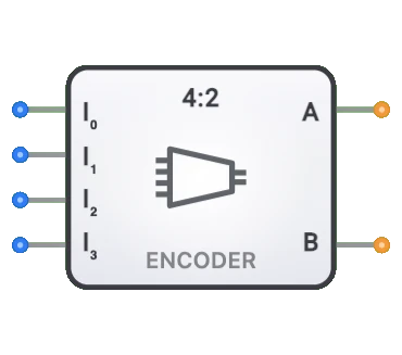
- 4-to-2 Encoder: Simpler version encoding four inputs to two outputs
- 16-to-4 Encoder: Larger version encoding sixteen inputs to four outputs
- Priority Encoder: Enhanced encoder that resolves multiple active inputs
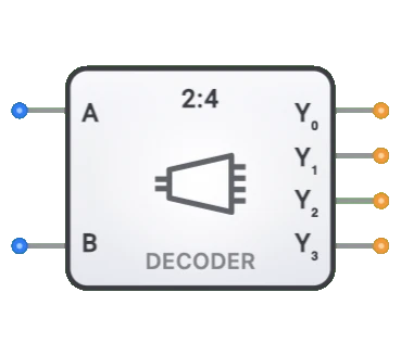
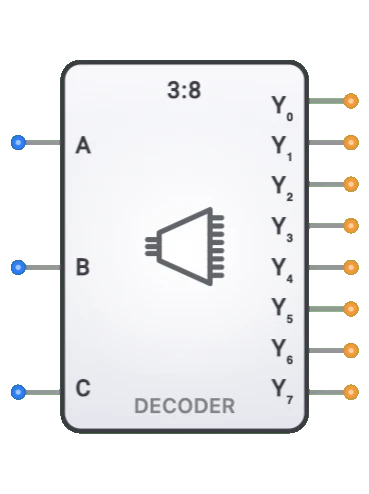
- 3-to-8 Decoder: Performs the inverse operation, converting binary to one-hot code
- BCD Encoder: Special encoder that converts decimal inputs to Binary Coded Decimal
- Multiplexer: Often used with encoders for data selection based on encoded values
- Binary Encoder: General term for encoders that convert to binary representation
- Keypad Encoder: Specialized encoder for keypad input processing