7-Segment Display (8-Pin)
Overview
- Purpose: The 8-Pin 7-Segment Display is a raw display component that allows direct control over each individual segment (a-g) and the decimal point (dp). Unlike the 4-pin Digit Display which includes a built-in decoder, this component exposes all 8 pins for granular control.
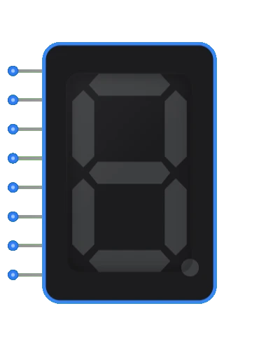
- Symbol: Represented as a rectangular block with 8 input pins on the left side and a 7-segment display visual output.
- DigiSim.io Role: Provides a lower-level interface for visualizing numeric and character data, ideal for teaching about display driving, decoding logic, and multiplexing.
Functional Description
Logic Behavior
The 8-Pin 7-Segment Display does not contain any decoding logic. Each input pin directly controls one of the 8 segments (7 segments + decimal point). A high signal (1) turns the segment ON, and a low signal (0) turns it OFF.
Segment Mapping:
| Pin Index | Segment | Position |
|---|---|---|
| 0 | a | Top |
| 1 | b | Top Right |
| 2 | c | Bottom Right |
| 3 | d | Bottom |
| 4 | e | Bottom Left |
| 5 | f | Top Left |
| 6 | g | Middle |
| 7 | dp | Decimal Point |
Inputs and Outputs
Inputs:
- Pin 0 (a): Controls the top segment.
- Pin 1 (b): Controls the top-right segment.
- Pin 2 (c): Controls the bottom-right segment.
- Pin 3 (d): Controls the bottom segment.
- Pin 4 (e): Controls the bottom-left segment.
- Pin 5 (f): Controls the top-left segment.
- Pin 6 (g): Controls the middle segment.
- Pin 7 (dp): Controls the decimal point.
Outputs:
- Visual Display: The segments light up corresponding to the active inputs.
Configurable Parameters
- Color: The active color of the segments (typically red, green, or blue).
- Size: The display size can be adjusted relative to other components.
Visual Representation in DigiSim.io
The component is shown as a rectangular block with 8 input pins arranged vertically on the left side. The 7-segment display is centered on the right.
      a
    ┌───┐
  f │   │ b
    │ g │
    ├───┤
  e │   │ c
    │   │
    └───┘
      d    . dp
Educational Value
Key Concepts
- Direct Segment Control: Understanding how individual segments form characters.
- Decoding Logic: Building custom decoders (e.g., BCD to 7-segment) using logic gates.
- Multiplexing: Learning how to drive multiple displays using shared data lines and control signals.
- Lookup Tables: Implementing character maps in ROM or software.
Learning Objectives
- Design a BCD to 7-segment decoder from scratch.
- Understand the difference between common anode and common cathode configurations (simulated via logic levels).
- Create custom character sets beyond standard 0-9 digits.
Usage Examples/Scenarios
- Custom Decoder Design: Students build the logic to convert 4-bit binary to the 7-segment signals.
- Alphanumeric Display: Displaying letters and custom symbols by driving specific segments.
- Running Text: Creating scrolling text effects by rapidly changing segment patterns.
- Status Indicators: Using individual segments to indicate different system states.
Technical Notes
- This component simulates a Common Cathode display where active high inputs turn on the segments.
- For Common Anode simulation, users would need to invert the input signals.
- The decimal point (dp) is independently controllable and often used for floating-point numbers.
Related Components
- Digit Display: A higher-level component with built-in BCD decoder.
- Decoder: Generic decoders that can be used to drive this display.
- ROM: Can be used to store segment patterns for character generation.