OR Gate
Overview
- Purpose: The OR gate performs a logical OR operation on its inputs. The output is HIGH (logical '1') if at least one input is HIGH. Only when all inputs are LOW (logical '0') is the output LOW.
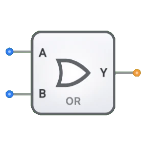
- Symbol: The OR gate is represented by a symbol with a curved input side and a pointed output side.
- DigiSim.io Role: Serves as a fundamental building block in digital logic circuits, implementing the Boolean OR operation.
Functional Description
Logic Behavior
The OR gate implements logical disjunction, producing a HIGH output when at least one of its inputs is HIGH.
Truth Table (for a 2-input OR gate):
| Input A | Input B | Output Y |
|---|---|---|
| 0 | 0 | 0 |
| 0 | 1 | 1 |
| 1 | 0 | 1 |
| 1 | 1 | 1 |
Boolean Expression: Y = A + B (Y equals A OR B)
Inputs and Outputs
- Inputs: The OR gate has 2 inputs (A, B).
- Output: A single 1-bit output representing the result of the OR operation.
Visual Representation in DigiSim.io
The OR gate is displayed with input pins on the left side and an output pin on the right side. When connected in a circuit, the component visually indicates the logic state of its pins through color changes on connecting wires.
Educational Value
Key Concepts
- Boolean Algebra: Reinforces the concept of the logical OR operator.
- Combinational Logic: Demonstrates a fundamental combinational logic circuit where the output depends solely on the current input values.
- Truth Tables: Helps understand how to read and interpret logic gate behavior through truth tables.
- Digital Circuit Analysis: Introduces concepts of how to analyze simple circuits with OR operations.
- Logic Design Fundamentals: Shows one of the three basic logic operations (AND, OR, NOT) used in digital electronics.
Learning Objectives
- Understand the logical OR operation and its truth table representation.
- Learn how OR gates serve as building blocks for more complex digital circuits.
- Recognize the difference between OR and other logic operations (AND, XOR, etc.).
- Apply the OR operation to solve real-world logic problems.
- Comprehend how OR gates fit into larger digital systems and combinational circuits.
Usage Examples/Scenarios
- Input Detection: Used to detect when any one of multiple inputs becomes active, such as in alarm systems where any sensor activation should trigger an alert.
- Error Monitoring: Combines error signals from different parts of a system to generate a unified error indicator.
- Signal Selection: When multiple sources can provide a valid signal, an OR gate selects any available signal.
- Enable Logic: Activating a subsystem when any of several enable conditions are met.
- Data Path Control: Creating conditional data paths in digital systems.
- Interrupt Systems: Combining multiple interrupt sources into a single interrupt signal.
Technical Notes
- The OR gate is a fundamental building block in digital systems and can be combined with NOT gates to form NOR gates.
- Multiple OR gates can be cascaded for handling more inputs than a single gate can accommodate.
- OR gates can be implemented using diodes, transistors, or in CMOS technology depending on the application.
- The propagation delay increases slightly with the number of inputs in physical implementations.
- In DigiSim.io, the OR gate's behavior accurately models the inclusive OR operation with appropriate timing.