Assembly Program Loader
Overview
- Purpose: The Assembly Program Loader is a specialized component that converts assembly language programs into binary machine code and loads them into memory components. It bridges the gap between human-readable assembly code and the binary instructions that digital circuits can process.
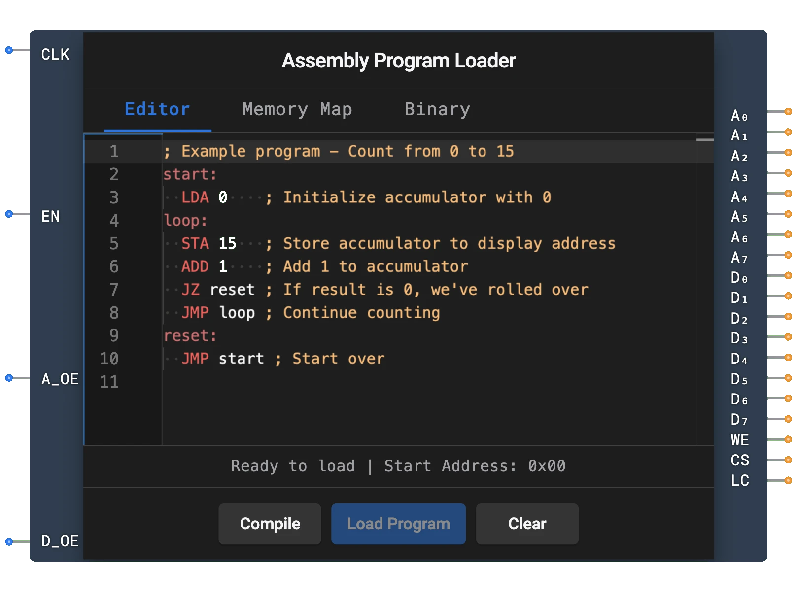
- Symbol: The Assembly Program Loader is represented by a rectangular block with inputs for clock, enable, address output enable, and data output enable, and outputs for address bus, data bus, write enable, chip select, and load complete.
- DigiSim.io Role: Enables testing and execution of assembly programs in CPU designs without manually converting code to binary, making it an essential educational tool for exploring computer architecture concepts.
Functional Description
Logic Behavior
The Assembly Program Loader reads assembly code entered by the user, converts it into machine code, and sequentially writes it to memory addresses. It operates in a state machine with distinct phases: idle, loading, and completion.
Operational Flow:
- When the loader is triggered (via its properties dialog), it begins the conversion process
- On each rising CLK edge while EN is HIGH, the loader advances to the next instruction
- During loading, the WE and CS outputs are HIGH
- When loading completes, the LC (Load Complete) output goes HIGH
- Address outputs are driven when A_OE is HIGH; data outputs are driven when D_OE is HIGH
Inputs and Outputs
Inputs (4 total):
- CLK: Pin 0. Clock input — the loader advances on each rising edge.
- EN (Enable): Pin 1. Overall enable for the loader. Loading only advances when HIGH.
- A_OE (Address Output Enable): Pin 2. When HIGH, address outputs (A0-A7) are driven; otherwise high-Z.
- D_OE (Data Output Enable): Pin 3. When HIGH, data outputs (D0-D7) are driven; otherwise high-Z.
Outputs (19 total):
- A0-A7: Pins 0-7. 8-bit address bus specifying the memory location to write to.
- D0-D7: Pins 8-15. 8-bit data bus containing the machine code instruction to be written to memory.
- WE: Pin 16. Write enable signal — HIGH during active loading.
- CS: Pin 17. Chip select signal — HIGH during active loading.
- LC (Load Complete): Pin 18. Goes HIGH when loading is finished.
Configurable Parameters
- Assembly Program: The user can enter and edit the assembly code through the component's properties dialog.
- Memory Size: The maximum number of instructions that can be loaded (typically limited by the connected memory component).
Visual Representation in DigiSim.io
The Assembly Program Loader is displayed as a rectangular block with labeled inputs on the left side (CLK, EN, A_OE, D_OE) and outputs on the right side (A0-A7, D0-D7, WE, CS, LC). When connected in a circuit, the component visually indicates its current state through the values shown on its outputs. The user can interact with the component through its properties dialog to enter and edit assembly code.
Educational Value
Key Concepts
- Assembly Programming: Introduces the fundamental concepts of assembly language programming.
- Machine Code Generation: Demonstrates how human-readable assembly instructions are converted to binary.
- Memory Management: Shows how programs are loaded sequentially into memory.
- Computer Architecture: Connects software concepts with hardware implementation.
- Instruction Set Architecture: Introduces the concept of instruction formats and encoding.
Learning Objectives
- Understand the relationship between assembly language and machine code.
- Learn how programs are loaded into memory for execution.
- Recognize the process of translating symbolic instructions to binary.
- Apply assembly programming concepts to create simple programs for CPU designs.
- Comprehend the interface between software and hardware in computer systems.
Usage Examples/Scenarios
- CPU Testing: Loading test programs to verify CPU functionality.
- Demonstration Circuits: Creating educational examples of computer architecture.
- Algorithm Implementation: Writing assembly programs to implement basic algorithms like counting, addition, or simple loops.
- Memory System Testing: Verifying memory read/write operations in a controlled manner.
- Instruction Set Exploration: Experimenting with different instruction types and their effects.
Technical Notes
- The Assembly Program Loader supports a simplified assembly language with common instructions (LDA, STA, ADD, SUB, JMP, JZ, JNZ, HLT).
- Labels in the assembly code are automatically resolved to memory addresses during the loading process.
- Specific memory locations can be initialized with data values using the @addr: value syntax.
- The loader processes instructions sequentially, so larger programs may require larger memory components.
- In DigiSim.io, the loader's behavior simulates the program loading phase of a real computer system, abstracting away the complexities of assemblers and linkers.
- Proper synchronization using the WE, CS, and LC signals is important when integrating the loader with other components.
Pins
| Pin Name | Type | Pin Index | Description |
|---|---|---|---|
| CLK | Input | 0 | Clock signal — loader advances on rising edge |
| EN | Input | 1 | Enable — loading advances only when HIGH |
| A_OE | Input | 2 | Address Output Enable — drives address bus when HIGH |
| D_OE | Input | 3 | Data Output Enable — drives data bus when HIGH |
| A0-A7 | Output | 0-7 | 8-bit address bus connecting to memory address inputs |
| D0-D7 | Output | 8-15 | 8-bit data bus connecting to memory data inputs |
| WE | Output | 16 | Write enable — HIGH during active loading |
| CS | Output | 17 | Chip select — HIGH during active loading |
| LC | Output | 18 | Load Complete — HIGH when loading is finished |
Usage
Connect the component to your ROM or RAM component:
- Connect A0-A7 outputs to the address input pins of your memory component
- Connect D0-D7 outputs to the data input pins of your memory component
- Connect WE to the write enable input of your memory component
- Connect CS to the chip select input of your memory component
Enter your assembly program in the component's properties dialog.
Connect CLK to a clock source and set EN, A_OE, and D_OE to HIGH to begin loading.
The component will automatically:
- Convert the assembly code to machine code
- Write the machine code to consecutive memory addresses starting from address 0
- Keep WE and CS HIGH during the loading process
- Set LC (Load Complete) to HIGH when complete
Wait for the LC signal before executing the program with your CPU.
Supported Assembly Language
The Assembly Program Loader supports a simple assembly language with the following instructions:
LDA addr    ; Load accumulator from memory address
STA addr    ; Store accumulator to memory address
ADD addr    ; Add value at memory address to accumulator
SUB addr    ; Subtract value at memory address from accumulator
JMP addr    ; Jump to address
JZ addr     ; Jump to address if accumulator is zero
JNZ addr    ; Jump to address if accumulator is not zero
HLT         ; Halt execution
Example Program
Here's an example program that counts from 1 to 10 and stores the result at memory address 15:
      LDA 14     ; Load 0 into accumulator (from address 14)
LOOP: ADD 13     ; Add 1 (from address 13)
      STA 15     ; Store result at address 15
      SUB 12     ; Subtract 10 (from address 12)
      JZ END     ; If result is zero (reached 10), jump to END
      LDA 15     ; Load current count back into accumulator
      JMP LOOP   ; Jump back to LOOP
END:  HLT        ; Halt

; Data section (must be included somewhere in program)
@12: 10          ; Value 10 at address 12
@13: 1           ; Value 1 at address 13
@14: 0           ; Value 0 at address 14
Tips
- The loader processes the program sequentially, writing each instruction to memory
- Labels (like LOOP: and END:) are automatically resolved to addresses
- Use @addr: value syntax to place specific values at specific addresses
- For larger programs, you may need to increase the size of your memory component
- Check the LC signal to ensure proper synchronization with your CPU
- The component supports comments using the semicolon (;) character