T Flip-Flop
Overview
- Purpose: The T Flip-Flop (Toggle Flip-Flop) is a sequential digital circuit that changes its output state when triggered by a clock edge while its T input is HIGH. It provides a simple and efficient way to implement toggling behavior for counters and frequency dividers.
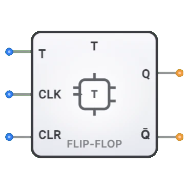
- Symbol: The T Flip-Flop is represented by a rectangular block with T (toggle) input, Clock (CLK) input, optional asynchronous SET and RESET inputs, and complementary outputs Q and Q̅.
- DigiSim.io Role: Serves as a fundamental building block for creating binary counters, frequency dividers, and state machines in digital circuits.
Functional Description
Logic Behavior
The T Flip-Flop toggles its output state when the T input is HIGH (1) during a positive clock edge (rising edge), or maintains its current state when T is LOW (0). It features an asynchronous clear input that can override the normal operation.
Pin Layout:
- Pin 0: T (Toggle control input)
- Pin 1: CLK (Clock input)
- Pin 2: CLR (Clear - asynchronous reset)
- Output 0: Q (stored value)
- Output 1: Q̅ (complementary output)
Truth Table (Positive Edge-Triggered T Flip-Flop):
| CLR | T | CLK | Q (next) | Q̅ (next) | Operation |
|---|---|---|---|---|---|
| 1 | X | X | 0 | 1 | Asynchronous Clear |
| 0 | 0 | ↑ | Q (prev) | Q̅ (prev) | Hold state (no change) |
| 0 | 1 | ↑ | Q̅ (prev) | Q (prev) | Toggle (complement) |
| 0 | X | 0 | Q (prev) | Q̅ (prev) | Hold state (no change) |
| 0 | X | ↓ | Q (prev) | Q̅ (prev) | Hold state (no change) |
Note: ↑ indicates rising edge of clock, ↓ indicates falling edge, X means "don't care", 0 = inactive (LOW), 1 = active (HIGH), "prev" means previous state
Operation Priority (highest to lowest):
- CLR (Clear): When CLR=1, Q is forced to 0 regardless of other inputs
- Clock Edge: When CLR=0, T input controls toggle behavior on rising clock edge
Note: This implementation does not include a PRE (Preset) pin. For preset functionality, use the JK or D flip-flop components.
Inputs and Outputs
Inputs:
- T (Toggle) [Pin 0]: 1-bit input that determines whether the flip-flop will toggle or maintain its state on the clock edge.
- CLK (Clock) [Pin 1]: 1-bit positive-edge timing signal that triggers state changes.
- CLR (Clear) [Pin 2]: 1-bit asynchronous input that forces Q to 0 when active HIGH.
Outputs:
- Q: 1-bit output representing the stored value (current state).
- Q̅: 1-bit output representing the complement of the stored value.
Configurable Parameters
- Clock Edge Sensitivity: Whether the flip-flop responds to rising or falling clock edges.
- Asynchronous Inputs: Whether Preset and Clear inputs are present and active-high or active-low.
- Propagation Delay: The time it takes for outputs to change after a triggering event.
Visual Representation in DigiSim.io
The T Flip-Flop is displayed as a rectangular block with labeled inputs on the left side (T, CLK, CLR from top to bottom) and outputs (Q and Q̅) on the right side. The component is clearly labeled with "T FF" to identify it as a T Flip-Flop. The clock input is typically marked with a triangle symbol indicating positive-edge sensitivity. When connected in a circuit, the component visually indicates its current state through the values shown on its outputs and color changes on connecting wires.
Educational Value
Key Concepts
- Toggle Behavior: Demonstrates the fundamental concept of binary state toggling.
- Sequential Logic: Illustrates how circuits can store and change state based on timing signals.
- Edge-Triggered Operation: Shows how digital circuits can respond to signal transitions rather than levels.
- Frequency Division: Introduces the concept of dividing frequencies using toggling behavior.
- Binary Counting: Demonstrates the basic building block for binary counters.
Learning Objectives
- Understand how the T Flip-Flop toggles between states based on input conditions.
- Learn how to create frequency divider circuits using T Flip-Flops.
- Recognize the role of T Flip-Flops in binary counter design.
- Apply T Flip-Flops in creating timing and sequence generation circuits.
- Comprehend how the T Flip-Flop relates to other flip-flop types (D, JK, SR).
Usage Examples/Scenarios
- Binary Counters: Creating counters by connecting T Flip-Flops in series.
- Frequency Division: Dividing a clock frequency by factors of 2 for timing applications.
- Square Wave Generation: Producing square waves with precisely half the frequency of the input.
- State Machines: Implementing alternating state sequences in control systems.
- Parity Generation: Creating parity bits for error detection in data transmission.
- Event Counting: Tallying the number of events by toggling between states.
Technical Notes
- A T Flip-Flop with T permanently connected to HIGH (1) functions as a frequency divider, producing an output frequency that is half the input clock frequency.
- T Flip-Flops can be constructed from other flip-flop types:
- Using a JK Flip-Flop with J and K inputs tied together as T
- Using a D Flip-Flop with an XOR gate that combines the T input with the current Q output
- Positive edge-triggered T Flip-Flops have specific setup and hold time requirements for reliable operation.
- Asynchronous Control: This implementation includes only a CLR (Clear) input which is active-HIGH. When CLR=1, the output is immediately forced to 0 regardless of other inputs.
- No Preset Pin: Unlike the JK and D flip-flops, this T flip-flop implementation does not include a PRE (Preset) input. For applications requiring preset functionality, use the JK or D flip-flop components.
- In cascaded arrangements (like counters), each T Flip-Flop typically toggles at half the frequency of the previous stage.
- In DigiSim.io, the T Flip-Flop provides visual feedback of toggling behavior, making it excellent for demonstrating binary counting concepts.
Characteristics
- Clock-Driven Operation:
- Edge-triggered (typically rising edge)
- State changes only on active clock transitions
- Toggle Function:
- When T=1: Output toggles with each clock edge
- When T=0: Output maintains its current state
- Propagation Delay:
- Clock-to-Q delay: Typically 5-15ns (technology dependent)
- Setup time: Time T must be stable before clock edge
- Hold time: Time T must be stable after clock edge
- Power Consumption:
- Static: Low (mainly leakage current)
- Dynamic: Moderate during state transitions
- Fan-Out:
- Typically 10-50 gates (technology dependent)
- Operational Modes:
- Toggle mode (T=1)
- Hold mode (T=0)
- Asynchronous preset/clear (when provided)
- Frequency Division:
- When T is held high, divides input clock frequency by 2
- Metastability Resistance:
- Better than latches due to edge-triggered behavior
- Internal master-slave structure reduces chance of metastability
Implementation Methods
- Using a JK Flip-Flop
- Connect both J and K inputs to T
- Inherits the edge-triggered properties of the JK flip-flop
graph LR
    T[T Input] --> J[J Input]
    T --> K[K Input]
    CLK[Clock] --> JKFF[JK Flip-Flop]
    J --> JKFF
    K --> JKFF
    JKFF --> Q[Q Output]
    JKFF --> QB[Q̅ Output]
Operation: When T=1 and clock triggers, flip-flop toggles. When T=0, flip-flop holds state.
- Using a D Flip-Flop with Feedback
- XOR gate combines T with current Q output
- Output fed back to D input
graph LR
    T[T Input] --> XOR[XOR Gate]
    Q[Q Output] --> XOR
    XOR --> D[D Input]
    D --> DFF[D Flip-Flop]
    CLK[Clock] --> DFF
    DFF --> Q
    DFF --> QB[Q̅ Output]
Operation: XOR creates toggle logic. When T=1, D = Q XOR 1 = NOT Q (toggles). When T=0, D = Q XOR 0 = Q (holds).
Direct Implementation Using Master-Slave Structure
- Two D latches in master-slave configuration
- Additional logic for the toggle function
Integrated Circuits
- Available in 74xx series logic families (e.g., 74LS73, 74HC73)
- Often implemented as dual or quad flip-flops per package
Applications
Binary Counters
- Frequency dividers (divide-by-2 when T=1)
- Ripple counters and synchronous counters
- Digital clock generation
Frequency Division
- Clock signal division for timing applications
- Rate multipliers and programmable dividers
State Machines
- Sequential logic circuits
- Control systems with alternating states
Parity Generation/Checking
- Even/odd parity bit generation
- Error detection in data transmission
Pulse Generation
- Square wave generators
- Timing and synchronization signals
Event Counting
- Counting external events or pulses
- Sensor input processing
Memory Elements
- Single-bit storage in digital systems
- Shift registers and data buffers
Limitations
Input Timing Constraints
- Setup and hold time requirements must be met
- Potential for timing violations in high-speed systems
Limited Functionality
- Only toggle or hold operations
- More complex behaviors require additional logic
Power Consumption During Toggling
- Continuous toggling (T=1) consumes more power
- May be a concern in battery-powered applications
Clock Skew Sensitivity
- Performance affected by clock distribution quality
- May require careful clock tree design in complex systems
Metastability Risk
- While better than latches, still susceptible to metastability
- Critical when interfacing asynchronous systems
Circuit Implementation Detail
T Flip-Flop Using JK Flip-Flop
The simplest implementation of a T flip-flop uses a JK flip-flop with both J and K inputs tied to the T input:
J = T
K = T
When T=0, J=K=0, which is the "hold" condition for a JK flip-flop. When T=1, J=K=1, which is the "toggle" condition for a JK flip-flop.
T Flip-Flop Using D Flip-Flop
A T flip-flop can also be constructed using a D flip-flop with an XOR gate:
D = T ⊕ Q
When T=0, D=Q, which maintains the current state. When T=1, D=¬Q, which causes the state to toggle.
Related Components
- D Flip-Flop: Edge-triggered flip-flop that directly loads input data
- JK Flip-Flop: Versatile flip-flop with set, reset, and toggle capabilities
- SR Flip-Flop: Basic flip-flop with set and reset inputs
- Binary Counter: Series of T flip-flops for counting
- Frequency Divider: Application of T flip-flop for dividing clock frequencies
- Johnson Counter: Special counter using T flip-flops with inverted feedback
- Ring Counter: Connected series of flip-flops with circular data path