Constant
Overview
- Purpose: The Constant component is a digital element that provides a fixed, unchanging binary HIGH (1) logic level. It serves as a permanent signal source without requiring user interaction or control.
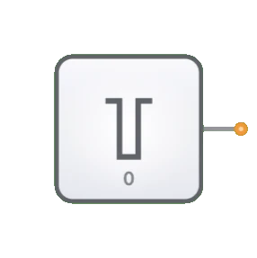
- Symbol: The Constant is represented by a small block with "1" indicated inside and a single output line.
- DigiSim.io Role: Serves as a simple but essential component for providing permanent logic levels in digital circuits where a consistent HIGH signal is needed.

Functional Description
Logic Behavior
The Constant component continuously outputs a fixed HIGH (1) signal that never changes during circuit operation.
Output State:
| Component | Output Value |
|---|---|
| Constant | 1 (HIGH) |
Inputs and Outputs
- Inputs: None. The Constant component has no inputs as it is designed to be a source-only component.
- Outputs:
- Output: 1-bit output that is permanently set to HIGH (1).
Configurable Parameters
- None. The Constant component is designed to be as simple as possible, providing a fixed HIGH (1) value without configuration options.
Visual Representation in DigiSim.io
The Constant is displayed as a small rectangular or square block with the value "1" clearly marked inside. It has a single output pin, typically on the right side. When connected in a circuit, the component's output wire is visually highlighted to indicate its active HIGH state.
Educational Value
Key Concepts
- Signal Sources: Demonstrates the concept of logic signal generation.
- Fixed Logic Levels: Illustrates the use of permanent signal values in digital design.
- Voltage References: Introduces the need for reference signals in digital systems.
- Boolean Constants: Represents the concept of logical TRUE in circuit design.
Learning Objectives
- Understand the role of constant signals in digital circuit design.
- Learn how to provide permanent control signals to various digital components.
- Recognize when to use constant values versus variable inputs in circuit design.
- Apply constant sources in combination with logic gates to create specific logical functions.
- Comprehend how constant values can simplify circuit design by eliminating unnecessary switches.
Usage Examples/Scenarios
- Pull-up Signals: Providing permanent HIGH signals for pull-up requirements.
- Enable Control: Permanently enabling functions or features in digital circuits.
- Select Line Fixing: Setting fixed values for multiplexer or decoder select lines.
- Logic Gate Control: Creating specific logic functions by fixing certain inputs.
- Setting Default States: Establishing default conditions in digital systems.
- Test and Reference Signals: Providing known logic levels for testing and comparison.
Technical Notes
- Unlike an Input Switch, the Constant cannot be toggled during circuit operation - it is permanently HIGH.
- In physical digital circuits, constant HIGH signals are typically implemented using connections to the power supply (VCC) through appropriate current-limiting resistors.
- When combined with logic gates, constant values can simplify circuit designs by reducing the number of required controllable inputs.
- The Constant has no propagation delay since its output is always available and unchanging.
- For applications requiring a permanent LOW (0) signal, the complementary Constant Zero component should be used instead.
Related Components
- Constant Zero: Provides a permanent LOW (0) signal instead of HIGH (1)
- Input Switch: Provides a user-controllable signal that can be toggled
- Clock: Provides a regularly alternating signal instead of a constant value
- Voltage Reference: Analog equivalent that provides a constant voltage level