8-bit ALU (Arithmetic Logic Unit)
Overview
- Purpose: The 8-bit ALU performs arithmetic and logical operations on 8-bit binary numbers. It serves as the computational core of digital systems, executing various operations based on control signals.
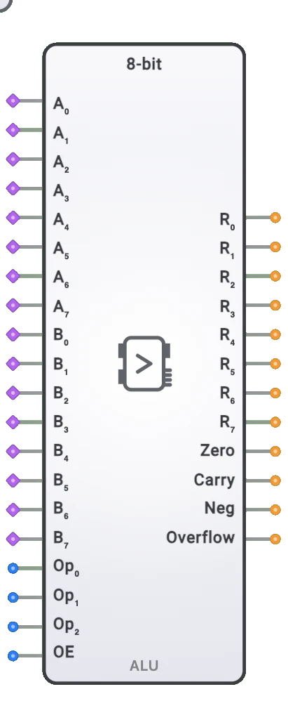
- Symbol: The ALU is represented by a rectangular block with inputs for two 8-bit operands (A and B) and operation selection, with outputs for the 8-bit result and status flags.
- DigiSim.io Role: The 8-bit ALU enables computation in digital circuits, making it essential for implementing processors, calculators, and other computational systems.
Functional Description
Logic Behavior
The 8-bit ALU takes two 8-bit inputs, performs an operation selected by the operation control inputs, and produces an 8-bit result along with status flags. These flags indicate properties such as whether the result is zero, negative, or if there was a carry or overflow.
Operation Selection:
| OP2 | OP1 | OP0 | Operation | Description |
|---|---|---|---|---|
| 0 | 0 | 0 | Y = A + B | Addition |
| 0 | 0 | 1 | Y = A - B | Subtraction |
| 0 | 1 | 0 | Y = A & B | Bitwise AND |
| 0 | 1 | 1 | Y = A | B | Bitwise OR |
| 1 | 0 | 0 | Y = A ^ B | Bitwise XOR |
| 1 | 0 | 1 | Y = ~A | Bitwise NOT (complement of A) |
| 1 | 1 | 0 | Y = A << 1 | Logical shift left |
| 1 | 1 | 1 | Y = A >> 1 | Logical shift right |
Inputs and Outputs
Inputs:
- A0-A7: 8-bit first operand.
- B0-B7: 8-bit second operand.
- OP0-OP2: 3-bit operation select to determine which function to perform.
- SubIn: Subtract input control signal.
Outputs:
- Y0-Y7: 8-bit result of the operation.
- Zero Flag (Z): Set when the result is zero (all bits are 0).
- Carry Flag (C): Set when an operation produces a carry-out (for addition) or borrow (for subtraction).
- Negative Flag (N): Set when the most significant bit of the result is 1 (negative in two's complement).
- Overflow Flag (V): Set when a signed arithmetic operation results in an overflow.
Configurable Parameters
- Propagation Delay: The time delay between input changes and the corresponding output changes. This is simulated in DigiSim.io.
Visual Representation in DigiSim.io
The 8-bit ALU is displayed as a rectangular block with inputs on the left side and outputs on the right side. It's clearly labeled "ALU-8BIT" to identify its function. Input pins (A0-A7, B0-B7, OP0-OP2) and output pins (Y0-Y7, Z, C, N, V) are arranged in logical groups. The component visually indicates the current state of all inputs and outputs.
Educational Value
Key Concepts
- Binary Arithmetic: Demonstrates how computers perform basic arithmetic operations on binary numbers.
- Boolean Logic: Shows the implementation of logical operations on multi-bit values.
- Status Flags: Introduces the concept of condition codes that provide information about operation results.
- Computational Building Blocks: Illustrates how complex operations can be implemented using digital logic.
Learning Objectives
- Understand how digital systems perform arithmetic and logical computations.
- Learn the relationship between binary operations and their results.
- Recognize how status flags provide essential information about operation outcomes.
- Apply ALU concepts to design simple computational systems.
- Comprehend how the ALU fits into the broader architecture of a computer system.
Usage Examples/Scenarios
- Simple CPU Design: The ALU forms the computational core of a CPU, executing arithmetic and logical operations.
- Calculator Circuits: Implementation of binary calculators that perform basic math operations.
- Data Manipulation: Processing data by performing bitwise operations for masking, filtering, or transforming values.
- Condition Testing: Using the ALU and its flags to test specific conditions in data values.
- Signal Processing: Basic digital signal processing operations like scaling, offset adjustment, and threshold detection.
Technical Notes
- Arithmetic Operations: Addition and subtraction are implemented using full adders with carry propagation.
- Flag Generation: Status flags are derived from the operation result and carry chain.
- Operational Latency: Different operations may have slightly different propagation delays, with addition and subtraction typically taking the longest due to carry propagation.
- Cascading: Multiple 8-bit ALUs can be connected together to perform operations on wider data (16-bit, 32-bit, etc.).
Characteristics
Input Configuration:
- Two 8-bit data inputs (A[7:0] and B[7:0])
- 3-bit operation select inputs (OP[2:0])
- Optional clock input for sequential operations
- Optional carry-in for chained arithmetic operations
- May include additional control signals for specialized functions
- Input loading consistent with logic family used
- All inputs typically use standard logic levels
Output Configuration:
- 8-bit result output (Y[7:0])
- Status flag outputs:
- Zero Flag (Z): Set when result is zero (all bits 0)
- Carry Flag (C): Set when operation produces a carry-out
- Overflow Flag (V): Set when signed arithmetic operation overflows
- Negative Flag (N): Set when result has MSB=1 (negative in two's complement)
- Optional carry-out for cascading multiple ALUs
- Standard logic level outputs
- Outputs capable of driving typical digital loads
- May include tri-state output capability
Functionality:
- Arithmetic operations: addition, subtraction, increment, decrement
- Logical operations: AND, OR, XOR, NOT
- Shift operations: logical left/right shift, rotate left/right
- Transfer operations: pass A, pass B, clear, set
- Operation selection via control inputs
- Flag generation for result status
- Combinational operation (unless registered)
- May support both unsigned and signed operations
- Cascadable for wider word widths
Propagation Delay:
- Varies by operation:
- Addition/Subtraction: 30-50ns (most complex paths)
- Logical operations: 15-25ns (typically faster)
- Shift operations: 20-35ns (moderate complexity)
- Critical path typically through carry propagation
- Flag generation adds additional delay
- Technology dependent (TTL, CMOS, etc.)
- Temperature and voltage sensitive
- Variations between maximum and typical delay
- Delay increases when cascaded for wider operations
- Varies by operation:
Fan-Out:
- Data outputs typically drive 10-20 standard loads
- Flag outputs may have lower drive capability
- Output loading affects propagation delay
- May require buffering for high fan-out situations
- Consistent with logic family specifications
- Critical signals may need special attention
Power Consumption:
- Moderate to high based on complexity
- Depends on technology (CMOS, TTL, etc.)
- Dynamic power increases with clock rate
- Operation-dependent (arithmetic typically higher)
- Input switching activity affects power
- Static power significant in older technologies
- Power increases with number of active gates
Circuit Complexity:
- High complexity due to multiple functions
- Requires significant logic resources
- Extensive internal datapaths
- Complex function selection logic
- Flag generation adds additional complexity
- Multiple internal stages
- Integrated designs reduce external component count
- Register integration increases complexity further
Implementation Methods
Discrete Logic Implementation
- Built from basic gates and MSI components
- Separate circuits for each operation type
- Multiplexers to select operation result
- Flag generation logic for each result
- Educational implementation to demonstrate ALU principles
- Significant component count
- Limited to lower speeds
- Valuable for understanding ALU architecture
Integrated Circuit Implementation
- Dedicated ALU ICs
- Examples: 74181 (4-bit ALU, cascadable), 74382
- Various features and operation sets
- Available in different logic families
- Reduced external component count
- Improved reliability over discrete designs
- Well-characterized timing and loading
- Often used in older or educational computer designs
Carry Lookahead Design
- Advanced carry propagation techniques
- Reduces critical path delay
- Parallel prefix adder structures
- Faster arithmetic operations
- More complex gate structure
- Increased gate count for performance
- Common in high-performance implementations
- Various carry lookahead schemes possible
Cascaded Implementation
- Multiple smaller ALUs combined
- Carry chaining between units
- Flag combination logic
- Modular approach to wider word sizes
- Uses standard components efficiently
- Balance of performance and complexity
- May have increased propagation delay
- Cost-effective for wider implementations
FPGA/ASIC Implementation
- HDL-based design (VHDL, Verilog)
- Optimized for target technology
- Takes advantage of dedicated arithmetic structures
- Configurable operation set
- Scalable to different bit widths
- Can leverage fast carry chains in FPGAs
- Customizable for specific requirements
- Resource-efficient implementation
Microcode-Controlled ALU
- Operations controlled by microcode
- More flexible operation set
- Potentially slower execution
- Complex operations broken into microoperations
- Common in CISC processor designs
- Easier to extend with new operations
- Higher control overhead
- Better suited for complex instruction sets
Bit-Slice Implementation
- Built from bit-slice processor components
- Modular design for different word widths
- Classical approach for custom processors
- Examples: AMD 2901, 74LS181
- Standardized interfaces between slices
- Flexible configuration options
- Well-suited for educational purposes
- Historically important architecture
Applications
Central Processing Units (CPUs)
- Core computational element
- Instruction execution
- Address calculation
- Program counter manipulation
- Conditional operations
- Loop control
- Flag generation for branching
Microcontrollers
- Embedded computation
- I/O processing
- Data conversion
- Protocol implementation
- Sensor data processing
- Control algorithms
- Real-time operations
Digital Signal Processing
- Signal filtering
- Transforms (FFT, DCT)
- Convolution operations
- Sample manipulation
- Coefficient multiplication
- Accumulation operations
- Signal generation
Graphics Processing
- Coordinate transformation
- Pixel manipulation
- Geometry calculations
- Blending operations
- Texture mapping
- Color space conversion
- Vector operations
Custom Computing Machines
- Application-specific processors
- Hardware accelerators
- FPGA-based computing
- Specialized algorithms
- Data flow architectures
- Parallel processing elements
- High-performance computing
Educational Systems
- Computer architecture learning
- Digital design teaching
- Hands-on processor design
- Algorithm implementation
- Performance analysis
- Hardware/software interface understanding
- Computing fundamentals
Testing and Verification
- Circuit testing
- Fault detection
- Logical comparison
- Signature analysis
- Built-in self-test
- Manufacturing testing
- Functional verification
Limitations
Performance Constraints
- Carry propagation delay limits arithmetic speed
- Sequential operation execution (one at a time)
- Fixed word size requires multi-cycle for larger operations
- Operation selection overhead
- Critical path through arithmetic operations
- Flag generation adds delay
- Operation speed varies by function
Architectural Limitations
- Limited operation set
- Fixed bit width requires cascading
- Basic operations require instruction sequencing for complex tasks
- Flag dependencies between operations
- Limited parallelism within the unit
- Operation granularity at word level
- General-purpose nature sacrifices specialized optimization
Implementation Challenges
- Complex control logic required
- Significant routing resources needed
- High gate count increases power consumption
- Testing complexity due to multiple operations
- Timing verification across all operations
- Performance vs. area tradeoffs
- Critical timing paths through carry chains
Operational Constraints
- No direct support for floating-point
- Limited precision (8-bit)
- Multi-precision arithmetic requires software algorithms
- No direct support for division or multiplication
- Complex operations require multiple steps
- Limited data type support
- Result flags may not be comprehensive
Scaling Issues
- Performance degrades with cascading
- Power increases with width
- Design complexity grows non-linearly
- Testing complexity increases exponentially
- Increased layout challenges
- Interconnect becomes critical
- Clock distribution more challenging
Circuit Implementation Detail
Basic ALU Block Diagram
graph LR
    A[A Operand<br/>8-bit] --> ARITH[Arithmetic Section<br/>Add/Sub]
    A --> LOGIC[Logic Section<br/>AND/OR/XOR]
    A --> SHIFT[Shift Section<br/>Left/Right]
    B[B Operand<br/>8-bit] --> LOGIC

    ARITH --> MUX[Multiplexer]
    LOGIC --> MUX
    SHIFT --> MUX

    OP[Operation Select<br/>OP2:0] --> CTRL[Control Logic]
    CTRL --> MUX

    MUX --> Y[Result<br/>Y 8-bit]
    CTRL --> FLAGS[Status Flags<br/>Z,C,N,V]
Flag Generation Logic
graph LR
    ResultY[Y 7:0] --> NorGate[NOR Gate] --> ZeroFlag[Zero Flag Z]
    ResultY7[Y bit 7] --> BufGate1[Buffer] --> NegFlag[Negative Flag N]

    CinPin[Carry In] --> XorGate[XOR Gate] --> OverFlag[Overflow Flag V]
    CoutPin[Carry Out] --> XorGate

    CoutPin --> BufGate2[Buffer] --> CarryFlag[Carry Flag C]
1-Bit ALU Slice (Basic Building Block)
Each bit slice contains:
- Arithmetic Unit: Full adder for addition/subtraction
- Logic Unit: AND, OR, XOR gates for logical operations
- Shift Unit: Connection to adjacent bit for shift operations
- Multiplexer: Selects result based on operation code
Operation Selection:
| OP2:0 | Selected Output |
|---|---|
| 000 | Addition result |
| 001 | Subtraction result |
| 010 | AND result |
| 011 | OR result |
| 100 | XOR result |
| 101 | NOT A result |
| 110 | Shift left result |
| 111 | Shift right result |
Related Components
- 4-bit ALU: Smaller version for nibble-sized operations
- 16-bit ALU: Extended version for word-sized operations
- 32/64-bit ALU: Larger versions for modern processors
- Barrel Shifter: Specialized component for multi-bit shifts
- Binary Adder: Focused component for addition only
- Logic Unit: Dedicated to logical operations only
- Multiplier: Specialized for multiplication operations
- Divider: Specialized for division operations
- Floating-Point Unit (FPU): Handles floating-point arithmetic
- SIMD ALU: Performs same operation on multiple data elements in parallel