XNOR Gate
Overview
- Purpose: The XNOR (Exclusive NOR) gate performs a logical equality operation on its inputs. The output is HIGH (logical '1') when all inputs have the same value (all HIGH or all LOW).
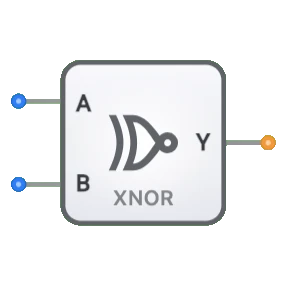
- Symbol: The XNOR gate is represented by a symbol similar to the XOR gate but with an additional small circle (bubble) at the output, indicating inversion.
- DigiSim.io Role: Serves as a fundamental component for comparators, parity checking circuits, and equivalence detection in digital systems.
Functional Description
Logic Behavior
The XNOR gate implements logical equivalence, producing a HIGH output when all inputs have the same state. For a two-input XNOR gate, the output is HIGH when both inputs are the same (both HIGH or both LOW).
Truth Table (for a 2-input XNOR gate):
| Input A | Input B | Output Y |
|---|---|---|
| 0 | 0 | 1 |
| 0 | 1 | 0 |
| 1 | 0 | 0 |
| 1 | 1 | 1 |
Boolean Expression: Y = A ⊙ B (Y equals A XNOR B)
Inputs and Outputs
- Inputs: The XNOR gate has 2 inputs (A, B).
- Output: A single 1-bit output representing the result of the XNOR operation.
Visual Representation in DigiSim.io
The XNOR gate is displayed with input pins on the left side and an output pin on the right side. Its symbol includes a double curved line on the input side (like the XOR gate) and a small circle (bubble) at the output indicating inversion. When connected in a circuit, the component visually indicates the logic state of its pins through color changes on connecting wires.
Educational Value
Key Concepts
- Logical Equivalence: Demonstrates the concept of equality comparison between binary values.
- Combinational Logic: Shows how a gate's output is determined solely by the current input values.
- Complementary Operations: Illustrates the relationship between XOR and XNOR as complementary functions.
- Even Parity: Introduces the concept of even parity checking in digital systems.
Learning Objectives
- Understand the logical equivalence operation and its truth table representation.
- Learn how XNOR gates can be used to detect when signals are identical.
- Recognize the relationship between XNOR gates and other logic gates (NOT, AND, OR, XOR).
- Apply XNOR gates in practical circuits like comparators and parity generators.
Usage Examples/Scenarios
- Bit Comparators: Detecting when two bits or bit patterns are identical.
- Even Parity Generation/Checking: Creating or verifying even parity bits for error detection.
- Phase Comparison: Detecting when two signals are in phase or have the same state.
- Equality Testing: Comparing multiple signals to determine if they all have the same value.
Technical Notes
- The XNOR gate's output exhibits high impedance (high-Z) if any of its inputs are in a high-Z state or undefined.
- For multi-input XNOR gates, the output is HIGH if an even number of inputs are HIGH (including zero), making it useful for even parity detection.
- While a basic logic gate in DigiSim.io, XNOR gates are typically implemented using combinations of AND, OR, and NOT gates, or by inverting the output of an XOR gate in physical circuits.
Characteristics
- Boolean Expression: Y = A ⊙ B (or A XNOR B)
- Algebraic Expression: Y = A·B + Ā·B̄
- Propagation Delay: Typically 8-17ns (varies by technology)
- Power Consumption: Low to moderate
- Fan-Out: Typically 10-50 gates (technology dependent)
- Noise Margin: Moderate
- Logic Levels: TTL/CMOS compatible
Types of XNOR Gates
Two-Input XNOR
- Standard configuration
- Used for equality comparison
Multi-Input XNOR
- Three or more inputs
- Used for detecting even parity
- Output is 1 when an even number of inputs are 1
Gated XNOR
- Has additional enable/control inputs
- Used in controlled operations
Open-Collector/Open-Drain XNOR
- Special output configuration for wired-AND capability
- Used in bus-oriented systems
Applications
Equality Comparators
- Bit-wise comparison of binary numbers
- Match detection circuits
Even Parity Generation/Checking
- Error detection in data transmission
- Memory system error checking
Phase Comparison
- Digital phase detectors
- Clock synchronization circuits
Arithmetic Operations
- One's complement systems
- Special arithmetic functions
Control Systems
- State detection
- Conditional operation triggering
Level Translation
- When combined with other gates
- Signal conversion between systems
Digital Signal Processing
- Correlation detection
- Pattern matching operations
Implementation Methods
Using Basic Gates
- Y = (A AND B) OR (NOT A AND NOT B)
- Requires AND, OR, and NOT gates
XOR Gate with Inverter
- Add an inverter to the output of an XOR gate
- Simple implementation when XOR gates are available
NAND/NOR Implementation
- Can be built using only NAND or only NOR gates
- NAND implementation: Y = ((A NAND B) NAND (A NAND A)) NAND ((B NAND B) NAND (A NAND B))
Integrated Circuits
- 74xx266: Quad 2-input XNOR gates
- 74xx520/521: 8-bit comparators (use XNOR functionality)
Transistor-Level Implementation
- CMOS: Uses complementary pairs of MOSFETs
- TTL: Uses bipolar junction transistors
Circuit Implementation (2-Input XNOR Using Basic Gates)
graph LR
    A[Input A] --> NOT1[NOT Gate]
    B[Input B] --> NOT2[NOT Gate]

    A --> AND1[AND Gate]
    B --> AND1

    NOT1 --> AND2[AND Gate]
    NOT2 --> AND2

    AND1 --> OR[OR Gate]
    AND2 --> OR

    OR --> Y[Output Y]
Logic: Y = A·B + Ā·B̄ (outputs HIGH when inputs are equal)
Boolean Equations
For a 2-input XNOR gate:
- Y = A ⊙ B (where ⊙ represents the XNOR operation)
- Y = A·B + Ā·B̄
- Y = (A + B̄) · (Ā + B)
- Y = (A ⊕ B)' (the complement of XOR)
- Y = A ≡ B (logical equivalence)
For a 3-input XNOR gate:
- Y = A ⊙ B ⊙ C
- Y = (A ⊕ B ⊕ C)'
- Y = A·B·C + A·B̄·C̄ + Ā·B·C̄ + Ā·B̄·C
Related Components
- XOR Gate: Complement of XNOR, outputs true when inputs are different
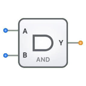
- AND Gate: Used in the construction of XNOR gates
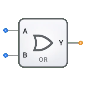
- OR Gate: Used in the construction of XNOR gates
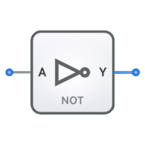
- NOT Gate: Used in the construction of XNOR gates
- Comparators: Use XNOR gates for bit-wise comparison
- Parity Generators/Checkers: Use XNOR gates for even parity
- Phase Detectors: Use XNOR gates for phase comparison
- Logic Equivalence Checkers: Use XNOR gates for functional verification