Comparator
Overview
- Purpose: The Comparator is a digital circuit that compares two binary numbers and produces outputs indicating their relative values (equal, greater than, or less than). It determines the relationship between two binary inputs and generates status signals based on this comparison.
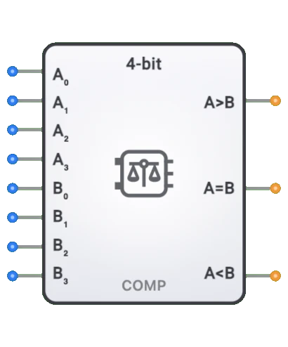
- Symbol: The Comparator is represented by a rectangular block with two inputs for the numbers being compared (A and B) and outputs indicating the comparison result (A=B, A>B, A<B).
- DigiSim.io Role: Serves as a fundamental decision-making component in digital circuits, enabling value comparison operations essential for implementing conditional logic, sorting networks, and control systems.
Functional Description
Logic Behavior
The Comparator examines two binary inputs and determines their relationship, asserting the appropriate output line to indicate whether the first input is equal to, greater than, or less than the second input.
Truth Table (for a 1-bit comparator):
| A | B | A=B | A>B | A<B | Relationship |
|---|---|---|---|---|---|
| 0 | 0 | 1 | 0 | 0 | Equal |
| 0 | 1 | 0 | 0 | 1 | Less than |
| 1 | 0 | 0 | 1 | 0 | Greater than |
| 1 | 1 | 1 | 0 | 0 | Equal |
Note: For multi-bit comparators, the comparison extends across all bits.
Inputs and Outputs
Inputs:
- A[n:0]: n-bit first operand for comparison.
- B[n:0]: n-bit second operand for comparison.
- Some implementations may include additional control inputs like enable (EN) or cascading inputs for building larger comparators.
Outputs:
- Equal (=): 1-bit output that is HIGH when A equals B.
- Greater (>): 1-bit output that is HIGH when A is greater than B.
- Less (<): 1-bit output that is HIGH when A is less than B.
Configurable Parameters
- Bit Width: The number of bits in the inputs being compared (1-bit, 4-bit, 8-bit, etc.).
- Comparison Mode: Whether the comparison is for unsigned binary numbers or signed (two's complement) numbers.
- Propagation Delay: The time it takes for outputs to change after input changes.
- Output Configuration: Some implementations may have active-low outputs or omit certain comparison results.
Visual Representation in DigiSim.io
The Comparator is displayed as a rectangular block with labeled inputs on the left side (A[n:0], B[n:0]) and outputs (=, >, <) on the right side. When connected in a circuit, the component visually indicates its comparison result through the values shown on its outputs and color changes on connecting wires.
Educational Value
Key Concepts
- Binary Comparison: Demonstrates how digital circuits determine the relationship between binary numbers.
- Decision Making: Illustrates how computers make comparisons that drive conditional operations.
- Magnitude Determination: Shows how the relative size of binary values is established in digital systems.
- Combinational Logic: Presents a practical application of combinational circuits with multiple outputs.
- Bitwise Operations: Introduces the concept of bit-by-bit comparison and how it determines overall number relationships.
Learning Objectives
- Understand how digital systems compare numeric values.
- Learn the implementation of comparison operations using logic gates.
- Recognize how comparison results drive decision-making in digital systems.
- Apply comparator concepts to design selection circuits, min/max finders, and range detectors.
- Comprehend the difference between unsigned and signed number comparison.
Usage Examples/Scenarios
- Conditional Branching: Determining whether to take a branch in a CPU based on comparing register values.
- Sorting Networks: Building blocks for arranging data in ascending or descending order.
- Limit Detection: Identifying when a value exceeds or falls below specific thresholds.
- Address Comparison: Determining when a memory address matches a specific value for decoding.
- Window Comparison: Detecting when a value falls within a specific range.
- Zero Detection: Identifying when a calculation result equals zero.
Technical Notes
- Simple 1-bit comparators are typically implemented using XOR gates (for equality) and AND gates with inverters (for inequality).
- Multi-bit comparators can be constructed as ripple comparators (simple but slower) or parallel comparators (faster but more complex).
- For signed number comparison, the most significant bit requires special handling as it represents the sign.
- Cascading multiple comparators allows comparison of wider binary numbers at the cost of increased propagation delay.
- In DigiSim.io, the comparator behavior models real-world digital components with proper handling of multi-bit inputs.
- For high-speed operation, look-ahead techniques similar to those in adders can be implemented to reduce comparison delay.
Applications
- Arithmetic Logic Units (ALUs) in processors
- Address comparison in memory systems
- Instruction decoding in CPUs
- Data sorting algorithms
- Window comparators in analog-to-digital converters
- Range checking in security and validation systems
- Password verification systems
- Magnitude comparison in control systems
- Equality testing in digital signal processors
- Branch prediction in pipeline processors
Implementation
Comparators can be implemented using:
- Basic logic gates (AND, OR, NOT, XOR)
- Specialized comparator ICs (74HC85, 74LS682, etc.)
- Programmable logic devices (FPGAs, CPLDs)
- Built-in ALU functions in microprocessors
- Various architectures:
- Ripple comparators (simpler but slower)
- Parallel comparators (faster but more complex)
- Tree-based architectures (balanced speed/complexity)
Circuit Implementation
A basic 1-bit comparator can be implemented with the following logic:
Equality Detection
graph LR
    A[A] --> XNOR[XNOR Gate]
    B[B] --> XNOR
    XNOR --> EQ[Equal A=B]
Greater Than Detection
graph LR
    A[A] --> AND1[AND Gate]
    BN[B'] --> AND1
    AND1 --> GT[Greater Than A>B]
Less Than Detection
graph LR
    AN[A'] --> AND2[AND Gate]
    B[B] --> AND2
    AND2 --> LT[Less Than A<B]
For multi-bit comparators, these circuits are combined with appropriate cascading logic.
Related Components
- Magnitude Comparator: Specialized for comparing the magnitude of binary numbers
- Equality Comparator: Focuses only on determining if two values are equal
- Window Comparator: Determines if a value falls within a specified range
- ALU: Contains comparison functionality among many other operations
- XNOR Gate: Used for bit-wise equality comparison
- Subtractor: Can be used for comparison by examining the sign of the difference