8-bit Counter
Overview
- Purpose: The 8-bit Counter is a sequential digital circuit that progresses through a sequence of 256 distinct states (0 to 255) upon the application of clock pulses. It counts upward and can hold its current value or be cleared based on control signals.
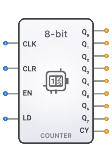
- Symbol: The 8-bit Counter is represented by a rectangular block with inputs for clock (CLK), clear (CLR), enable (EN), and load (LD), with eight data outputs representing the current count value and a carry output.
- DigiSim.io Role: Serves as an essential component for implementing timing, sequencing, and counting functions in digital systems, providing a wider range (256 states) than smaller counters for applications requiring more counting states.
Functional Description
Logic Behavior
The 8-bit Counter increments through a binary sequence on each rising clock edge when enabled. It counts upward only. When cleared, the counter returns to zero asynchronously regardless of the clock.
Operation Table:
| CLR | EN | CLK | Operation | Output Effect |
|---|---|---|---|---|
| 1 | X | X | Clear (async) | Q = 0 |
| 0 | 1 | ↑ | Count up | Q[n+1] = Q[n] + 1 |
| 0 | 0 | ↑ | Hold | Q[n+1] = Q[n] |
| 0 | X | 0 | No change | Q[n+1] = Q[n] |
Note: ↑ represents a rising clock edge, X represents a "don't care" condition. The counter wraps from 255 to 0.
Inputs and Outputs
Inputs:
- CLK (Clock): Pin 0. Triggers the counter on the rising edge.
- CLR (Clear): Pin 1. Asynchronously resets the counter to 0 when HIGH.
- EN (Enable): Pin 2. Enables counting when HIGH.
- LD (Load): Pin 3. Reserved for future use (parallel load not currently supported).
Outputs:
- Q[7:0]: 8-bit output representing the current count value (Q0=LSB, Q7=MSB).
- Carry: 1-bit output that goes HIGH when the counter reaches its maximum value (255).
Configurable Parameters
- Clock Edge Sensitivity: Whether the counter responds to rising or falling clock edges.
- Reset Type: Whether the reset is synchronous (only on clock edges) or asynchronous (immediate).
- Reset Value: The value the counter resets to (typically zero).
- Count Sequence: Whether the counter follows a binary, BCD, or other counting sequence.
- Propagation Delay: The time it takes for outputs to change after a triggering event.
Visual Representation in DigiSim.io
The 8-bit Counter is displayed as a rectangular block with labeled inputs on the left side (CLK, RST, EN, UP/DOWN) and outputs (Q[7:0], COUT) on the right side. The clock input is typically marked with a triangle symbol indicating edge sensitivity. When connected in a circuit, the component visually indicates its current state through the binary value shown on its outputs and color changes on connecting wires.
Educational Value
Key Concepts
- Sequential Logic: Demonstrates how digital circuits maintain and update state over time.
- Binary Counting: Illustrates the progression through binary number sequences.
- Synchronous Operation: Shows how clock signals coordinate and synchronize digital operations.
- Modular Arithmetic: Presents the concept of rollover/wraparound when a counter exceeds its range.
- Control Logic: Introduces the use of enable and direction controls to modify circuit behavior.
Learning Objectives
- Understand how counters progress through binary sequences and maintain state.
- Learn how control signals like reset, enable, and direction affect counter operation.
- Recognize the difference between synchronous and asynchronous counter designs.
- Apply 8-bit counters in designing timers, sequencers, and address generators.
- Comprehend the concept of counter overflow/underflow and how carry outputs signal these conditions.
Usage Examples/Scenarios
- Address Generation: Sequentially accessing memory locations in a CPU or controller.
- Timer Implementation: Creating precise time delays or measuring time intervals.
- Event Counting: Tallying occurrences of events or pulses in digital systems.
- Frequency Division: Dividing an input clock frequency by a programmable factor.
- State Sequencing: Implementing the sequencing logic for finite state machines.
- Data Acquisition: Controlling the timing for sampling analog signals.
- Digital Control Systems: Generating timing sequences for control operations.
Technical Notes
- The 8-bit counter can be implemented using various architectures:
- Asynchronous (Ripple) Counter: Simple but has propagation delay issues across bit positions.
- Synchronous Counter: All flip-flops change simultaneously, providing more reliable timing.
- An 8-bit binary counter can represent values from 0 to 255 before rolling over.
- The maximum operating frequency is limited by the propagation delay through the counter's logic.
- Counters can be cascaded to create wider counters (16-bit, 32-bit) by connecting the carry output of one counter to the enable of the next.
- Special counter configurations like Johnson counters or ring counters provide different counting sequences for specific applications.
- In DigiSim.io, the counter's behavior simulates real-world digital components with proper handling of control inputs and synchronous operation.
Characteristics
Input Configuration:
- Clock input (CLK): Triggers state transitions, typically active on rising edge
- Reset input (RST): Asynchronously resets counter to zero when asserted
- Enable input (EN): Enables or disables counting operation
- Direction control (UP/DOWN): Determines count direction (up when high, down when low)
- Compatible with standard digital logic levels
- May include additional inputs in some implementations (load, preset, etc.)
- Typical clock frequency range: DC to 50+ MHz depending on technology
Output Configuration:
- Eight state outputs (Q0-Q7)
- Carry/borrow output (Cout) - asserted when counter overflows (up) or underflows (down)
- Each output represents one bit of the current count value
- Q0 is the least significant bit (LSB), Q7 is the most significant bit (MSB)
- Capable of driving standard digital loads
- May include complementary outputs in some implementations
Functionality:
- Counts through binary sequence from 0 to 255 (or 255 to 0)
- Full 8-bit range provides 256 distinct states
- Wraps around from 255 to 0 when counting up
- Wraps around from 0 to 255 when counting down
- Carry output generated on wrap-around conditions
- Can be configured for different counting sequences
- Modulo-N counting possible with additional logic
Propagation Delay:
- Clock-to-output: 15-35ns typical
- Setup time: 10-20ns before clock edge
- Hold time: 0-10ns after clock edge
- Reset-to-output: 10-25ns
- Technology dependent (TTL, CMOS, etc.)
- Synchronous designs have consistent output timing
- Higher delays in cascaded asynchronous implementations
Fan-Out:
- Typically drives 10-20 standard loads
- Output loading affects propagation delay
- May require buffering for high fan-out applications
- Modern CMOS implementations have improved drive capability
Power Consumption:
- Static power minimal in CMOS implementations
- Dynamic power increases with clock frequency
- Proportional to number of bits that change state
- Higher than 4-bit counters due to additional flip-flops
- Power management features in many implementations
- Can be significant in high-speed applications
Circuit Complexity:
- Moderate to high complexity
- Requires eight flip-flops plus control logic
- Synchronous designs more complex than asynchronous
- Additional logic for features like parallel load
- Complexity increases with feature set
- Integrated versions reduce external component count
Implementation Methods
Asynchronous (Ripple) Counter
- Cascade of eight flip-flops (typically T or JK type)
- Each flip-flop output drives the clock of the next
- Simple implementation but with propagation delay issues
- The LSB changes on every clock, higher bits change when driven
- Not suitable for high-speed applications
- Glitches can occur during transitions
- The simplest design but with timing limitations
Synchronous Counter
- All flip-flops share a common clock
- State transitions occur simultaneously
- Additional combinational logic determines which flip-flops toggle
- More complex than ripple design but with better timing
- Higher speed operation than asynchronous designs
- Predictable timing behavior
- Can be implemented with D, JK, or T flip-flops
Up/Down Binary Counter
- Bidirectional counting capability
- Direction control logic for each flip-flop
- Additional complexity for direction control
- Common in application-specific counters
- Synchronous implementation preferred for reliable operation
- Carry/borrow logic for both counting directions
Presettable Counter
- Includes parallel load capability
- Data inputs for each bit
- Load enable control signal
- Can be initialized to any value
- Useful for timing specific intervals
- Additional multiplexers for load path
- Common in programmable timer applications
Binary Coded Decimal (BCD) Counter
- Modified 8-bit counter with two BCD decades
- Counts from 0 to 99 in decimal
- Reset logic for each 4-bit section at count 10
- Useful for human-readable counting applications
- Common in displays and user interfaces
- More complex decoding logic
Integrated Circuit Implementation
- Available as dedicated counter ICs
- Common in 74xx series (74LS590, 74HC590, 74HC393 cascaded)
- Various features: presettable, cascadable, up/down
- Different technologies for various speed/power requirements
- May include additional features like tri-state outputs
- Reduces component count in system designs
FPGA/ASIC Implementation
- Efficient implementation using flip-flops and LUTs
- Highly configurable and optimizable
- Easy to add specialized features
- Often synthesized from HDL descriptions
- Resource-efficient in modern programmable logic
- Can be tailored for specific timing requirements
Applications
Memory Addressing
- Program counter in microcontrollers and CPUs
- Address generation for sequential memory access
- DRAM refresh counters
- Stack pointers in computing systems
- DMA controllers for memory transfers
- Sequencing through memory locations
Timing Generation
- Precision timing intervals (up to 256 clock cycles)
- Programmable delay generation
- Pulse width control
- System timing coordination
- Real-time clock subsystems
- Timeout generation
Frequency Division
- Clock dividers with division ratios up to 256
- Precision frequency synthesis
- Signal generators
- Baud rate generators for communication
- Clock management in digital systems
- Frequency scaling
Event Counting
- High-range event tallying
- Pulse counting in instrumentation
- Revolution counting
- Flow measurement
- Occurrence rate monitoring
- Production line counting
Digital Control Systems
- State machine implementation
- Sequencing control operations
- Motor control timing
- Process controllers
- Industrial automation sequencing
- Time-based control algorithms
Data Acquisition
- Sample timing control
- ADC control sequencing
- Data buffering addresses
- Measurement trigger generation
- Sampling rate control
- Averaging counter for noise reduction
Communication Systems
- Frame counter for data packets
- Byte sequencing in serial protocols
- Communication timing
- Protocol sequencing
- Error detection counters
- Bit timing generators
Limitations
Timing Constraints
- Maximum operating frequency limited by technology
- Setup and hold time requirements for reliable operation
- Clock skew concerns in complex systems
- Propagation delay accumulation in asynchronous designs
- Reset recovery timing requirements
- Inconsistent timing across all bits in ripple implementations
Glitches and Race Conditions
- Output glitches during transitions (especially in asynchronous designs)
- Intermediate states during multi-bit transitions
- Critical in control applications
- Potential false triggering of downstream logic
- Hazards in output decoding logic
- Race conditions in counter feedback paths
Range Limitations
- Limited to 8-bit values (0-255)
- Requires cascading for larger counting ranges
- Overflow handling for counts exceeding range
- Extra logic needed for non-binary sequences
- Modulo-N counting requires additional logic
- Inefficient for small counting ranges
Power Consumption
- High dynamic power at fast clock rates
- Power spikes during multiple bit transitions
- Significant in battery-powered applications
- Increases with switching frequency
- Higher than smaller counters due to more flip-flops
- Thermal considerations in high-speed operations
Design Complexity
- More complex than smaller counters
- Advanced features increase logic requirements
- Synchronous designs require more combinational logic
- Testing and verification complexity
- Increased component count or logic resources
- Complex timing analysis for critical applications
Circuit Implementation Detail
8-bit Synchronous Binary Up Counter
graph TB
    Clock[Clock CLK] --> FlipFlop0[Flip-Flop 0]
    Clock --> FlipFlop1[Flip-Flop 1]
    Clock --> FlipFlop2[Flip-Flop 2]
    Clock --> DOTS[...]
    Clock --> FlipFlop7[Flip-Flop 7]

    Reset[Reset RST] --> FlipFlop0
    Reset --> FlipFlop1
    Reset --> FlipFlop2
    Reset --> DOTS
    Reset --> FlipFlop7

    FlipFlop0 --> OutputQ0[Q0]
    FlipFlop1 --> OutputQ1[Q1]
    FlipFlop2 --> OutputQ2[Q2]
    DOTS --> QDOTS[...]
    FlipFlop7 --> OutputQ7[Q7]

    ControlLogic[Enable & Clock<br/>Control Logic]
    Enable[Enable EN] --> ControlLogic
    UpDown[UP/DOWN] --> ControlLogic
    ControlLogic -.-> FlipFlop0
    ControlLogic -.-> FlipFlop1
    ControlLogic -.-> FlipFlop2
    ControlLogic -.-> FlipFlop7
74HC590 8-bit Binary Counter with Output Register
    ┌─────────────────┐
    │                 │
    │     74HC590     │
    │                 │
CLK ┤CP            Q0 ├── Q0
    │                 │
MR  ┤MR            Q1 ├── Q1
    │                 │
    │               Q2 ├── Q2
    │                 │
    │               Q3 ├── Q3
    │                 │
    │               Q4 ├── Q4
    │                 │
    │               Q5 ├── Q5
    │                 │
    │               Q6 ├── Q6
    │                 │
    │               Q7 ├── Q7
    │                 │
CEP ┤CEP              │
    │                 │
CET ┤CET          Q7S ├── Cout
    │                 │
OE  ┤OE               │
    │                 │
RCK ┤RCK              │
    │                 │
    └─────────────────┘
CP = Clock Pulse input, MR = Master Reset, CEP/CET = Count Enable inputs, OE = Output Enable, RCK = Register Clock, Q7S = Carry output
Related Components
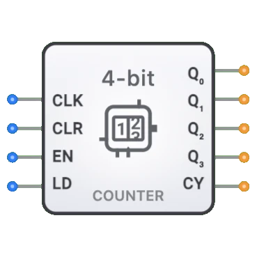
- 4-bit Counter: Smaller counter with range 0-15
- 16-bit Counter: Extended counter with range 0-65535
- BCD Counter: Counts in decimal digit sequences
- Up/Down Counter: Bidirectional counter with direction control
- Loadable Counter: Counter with parallel data loading capability
- Johnson Counter: Shift register with inverted feedback, with one bit change per state
- Ring Counter: Shift register with direct feedback, circulating a single bit
- Cascaded Counter: Multiple counters connected to extend counting range
- Frequency Divider: Counter used specifically for clock division
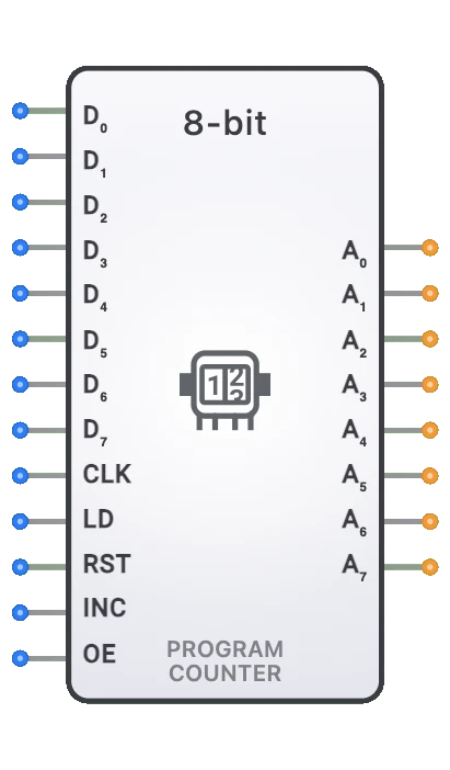
- Program Counter: Specialized counter for instruction sequencing in processors