Counter
Overview
- Purpose: The Counter is a sequential digital circuit that progresses through a predetermined sequence of states upon receiving clock pulses. It increments, decrements, or follows a specific pattern, storing each value as a binary number.
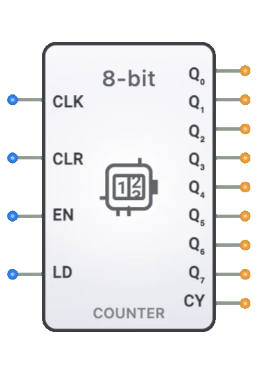
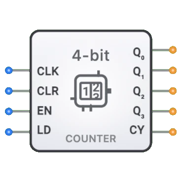
- Symbol: The Counter is represented by a rectangular block with clock (CLK), clear (CLR), and enable (EN) inputs, along with multiple output bits (Q0-Q3) and a carry output.
- DigiSim.io Role: Serves as a fundamental sequential building block for creating timing, counting, and control circuits in digital systems.
Functional Description
Logic Behavior
The Counter changes its state on clock edges according to control inputs, typically following a binary counting sequence.
Operation Table:
| CLK | CLR | EN | Operation | Output Effect |
|---|---|---|---|---|
| X | 1 | X | Clear (async) | Q = 0 |
| ↑ | 0 | 1 | Count up | Q[n+1] = Q[n] + 1 |
| ↑ | 0 | 0 | Hold | Q[n+1] = Q[n] |
| ↓ | 0 | X | No change | Q[n+1] = Q[n] |
Note: ↑ indicates rising edge, ↓ indicates falling edge, X means "don't care". The counter only counts upward and wraps from maximum value back to 0.
Inputs and Outputs
Inputs:
- CLK (Clock): Pin 0. Triggers state transitions on the rising edge.
- CLR (Clear): Pin 1. Asynchronously resets the counter to zero when HIGH.
- EN (Enable): Pin 2. Enables counting when HIGH.
- LD (Load): Pin 3. Reserved for future use (parallel load not currently supported).
Outputs:
- Q0-Q3: 4-bit output representing the current count value in binary.
- Carry: 1-bit output that goes HIGH when the counter reaches its maximum value (15 for 4-bit).
Configurable Parameters
- Counter Width: The number of bits in the counter, determining its maximum count range (e.g., 4-bit: 0-15).
- Count Direction: Whether the counter increments, decrements, or both.
- Modulus: The maximum count value before wrapping around (e.g., modulo-10 for decimal counting).
- Propagation Delay: The time it takes for outputs to update after a clock edge.
Visual Representation in DigiSim.io
The Counter is displayed as a rectangular block with inputs on the left side and outputs on the right side. The clock input is typically marked with a triangle symbol indicating edge sensitivity. When connected in a circuit, the component visually indicates its current state through the binary values displayed on its outputs and color changes on connecting wires.
Educational Value
Key Concepts
- Sequential Logic: Demonstrates how circuits can maintain and change state over time.
- Binary Counting: Illustrates binary number representation and arithmetic.
- Clock-Driven Operation: Shows how clock signals control timing in digital systems.
- State Machines: Introduces the concept of finite state machines and state transitions.
- Feedback Systems: Demonstrates how output values influence future states.
Learning Objectives
- Understand how counters maintain and update state based on clock signals.
- Learn the difference between asynchronous and synchronous counter operation.
- Recognize how counters are used for timing, counting, and control applications.
- Apply counters to design frequency dividers, timers, and state sequencers.
- Comprehend the relationship between clock frequency, enable control, and counting speed.
Usage Examples/Scenarios
- Frequency Division: Dividing a clock signal into lower frequencies.
- Event Counting: Tallying occurrences of external events.
- Timing Generation: Creating precise time delays and timing signals.
- Memory Addressing: Generating sequential memory addresses for access operations.
- Control Sequencing: Coordinating the timing of operations in digital systems.
- Digital Waveform Generation: Creating periodic digital signals with specific patterns.
Technical Notes
- Counters can be implemented in two main architectures: asynchronous (ripple) and synchronous. Synchronous counters update all bits simultaneously on a clock edge, providing glitch-free operation at the cost of increased complexity.
- The maximum counting frequency is limited by propagation delays through the counter logic.
- For larger counting ranges, multiple counters can be cascaded using the carry output of one counter to enable the next.
- The reset input typically takes precedence over all other inputs, immediately clearing the counter regardless of clock or enable states.
- In DigiSim.io, counters operate at a speed suitable for visual observation, whereas actual hardware counters can operate at much higher frequencies.
Characteristics
Input Configuration:
- Clock input (CLK): Triggers state transitions
- Reset input (RST): Asynchronously resets counter to zero
- Enable input (EN): Enables/disables counting operation
- Direction control (UP/DOWN): Determines count direction (up or down)
- Compatible with standard digital logic levels
- Edge-triggered operation (typically rising edge)
Output Configuration:
- Multiple state outputs (Q0-Q3 for a 4-bit counter)
- Carry/borrow output (Cout) - asserted when counter wraps around
- Each output reflects the current binary count value
- Capable of driving standard digital loads
- Usually available in both synchronous and asynchronous versions
Functionality:
- Sequentially steps through binary values upon clock transitions
- Binary counting sequence (0, 1, 2, 3, ...)
- Wrap-around behavior at maximum/minimum count
- Can be configured for different counting sequences
- Can count up, down, or both depending on design
- Modulo-N counting capability (counters with specific maximum values)
Propagation Delay:
- Clock-to-output: 10-25ns typical
- Setup time: 5-15ns before clock edge
- Hold time: 0-5ns after clock edge
- Reset-to-output: 5-20ns
- Technology dependent (TTL, CMOS, etc.)
- Varies with counter size and implementation
Fan-Out:
- Typically drives 10-20 standard loads
- Output loading affects propagation delay
- May require buffering for high fan-out applications
Power Consumption:
- Static power minimal in CMOS implementations
- Dynamic power increases with clock frequency
- Proportional to number of bits that change state
- Higher in synchronous designs at high frequencies
- Enable input can be used for power management
Circuit Complexity:
- Moderate (requires flip-flops plus control logic)
- Synchronous designs more complex than asynchronous
- Complexity increases with counter width
- Additional features (load, clear, etc.) increase complexity
- Specialized counting sequences require additional logic
Implementation Methods
Asynchronous (Ripple) Counter
- Built from cascaded flip-flops, usually T or JK type
- Each flip-flop output drives the clock of the next
- Simple design with minimal components
- Propagation delay accumulates through stages
- Not suitable for high-speed applications
- Suffers from glitches during transitions
Synchronous Counter
- All flip-flops share a common clock
- State transitions occur simultaneously
- Requires additional combinational logic
- Higher speed operation than asynchronous designs
- More predictable timing behavior
- Commonly implemented with JK or D flip-flops
Decade Counter (BCD Counter)
- Counts from 0 to 9 (modulo-10)
- Used for decimal counting applications
- Often constructed with feedback to reset at count 10
- Common in display and timing applications
- May feature BCD coded outputs
Johnson Counter (Twisted Ring Counter)
- Special sequence with only one bit changing at a time
- Useful for state machines and control applications
- Requires fewer decoding gates for state detection
- Provides 2n states with n flip-flops
- Better noise immunity due to Hamming distance of 1
Ring Counter
- Circulating "1" in a field of "0"s
- Used for sequencing operations
- One-hot encoded output (only one bit active at a time)
- Simple decoding logic
- Requires initialization
- Inefficient for large counts (n flip-flops for n states)
Integrated Circuit Implementation
- Available as dedicated counter ICs
- Common in 74xx series (74160-74169, 74190-74193)
- Various features: presettable, cascadable, up/down, etc.
- Different technologies for various speed/power requirements
- May include additional features like tri-state outputs
FPGA/ASIC Implementation
- Implemented using flip-flops and LUTs
- Highly configurable and optimizable
- Can implement specialized counting sequences
- Often synthesized from HDL descriptions
- Resource-efficient in modern programmable logic
Applications
Timing and Control
- Clock division
- Pulse generation
- Time delay implementation
- Sequencing control operations
- State machine implementation
Frequency Division
- Clock dividers for lower frequency generation
- Prescalers in timer circuits
- Frequency synthesis
- Digital tuning systems
- Clock management in digital systems
Memory Addressing
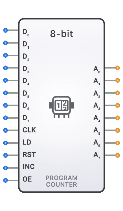
- Program counter in CPUs
- Address generation for sequential memory access
- Refresh counters in dynamic memory
- Stack pointer implementation
- DMA controllers
Event Counting
- Counting external events
- Pulse counting in instrumentation
- Tally systems
- Occurrence measurement
- Traffic flow monitoring
Data Conversion
- Analog-to-digital converters (successive approximation)
- Pulse width modulation generation
- Digital waveform generation
- Signal processing algorithms
- Pseudorandom sequence generation
Display Systems
- LED/LCD digit multiplexing
- Display refresh control
- Scanning in matrix displays
- Timing for video generation
- Character generation
Instrumentation and Measurement
- Frequency counters
- Period measurement
- Digital timers and stopwatches
- Pulse counting
- Scientific instrumentation
Limitations
Timing Constraints
- Setup and hold time requirements
- Clock skew sensitivity in synchronous designs
- Maximum operating frequency limitations
- Propagation delay through counter stages
- Reset recovery requirements
Glitches and Race Conditions
- Output glitches during transitions in asynchronous designs
- Critical in control applications
- May require synchronization with system clock
- Multiple output transitions not simultaneous in asynchronous designs
- Decoding glitches possible during transitions
Power Consumption
- Dynamic power increases with frequency
- High power in continuously running applications
- Power spikes during multiple bit transitions
- Standby power in always-on systems
- Battery life concerns in portable applications
Noise Susceptibility
- Sensitive to noise on clock line
- False counting due to noise
- Input debouncing required for mechanical inputs
- Electromagnetic interference concerns
- Ground bounce in high-speed designs
Counter Limitations
- Maximum count range limited by bit width
- Initialization requirements
- Specific sequence counters need additional logic
- Cascading complexity for larger counting ranges
- Overhead in specialized counting sequences
Circuit Implementation Detail
4-bit Synchronous Up Counter
graph TB
    CLK[Clock CLK] --> FF0[Flip-Flop 0]
    CLK --> FF1[Flip-Flop 1]
    CLK --> FF2[Flip-Flop 2]
    CLK --> FF3[Flip-Flop 3]

    RST[Reset RST] --> FF0
    RST --> FF1
    RST --> FF2
    RST --> FF3

    FF0 --> Q0[Q0]
    FF1 --> Q1[Q1]
    FF2 --> Q2[Q2]
    FF3 --> Q3[Q3]

    EN[Enable Logic<br/>AND Gates] -.-> FF0
    EN -.-> FF1
    EN -.-> FF2
    EN -.-> FF3
74LS193 4-bit Synchronous Up/Down Counter
    ┌───────────────────┐
    │                   │
    │      74LS193      │
    │                   │
    │                   │
CLK ┤CP↑           Q0   ├── Q0
    │                   │
MR  ┤MR            Q1   ├── Q1
    │                   │
D0  ┤D0            Q2   ├── Q2
D1  ┤D1            Q3   ├── Q3
D2  ┤D2                 │
D3  ┤D3            TC↑  ├── Cout
    │                   │
PE  ┤PE            TC↓  ├── Bout
    │                   │
CPU ┤CPU                │
CPD ┤CPD                │
    │                   │
    └───────────────────┘
CP↑ = Count Up Clock, CPD = Count Down Clock, MR = Master Reset, PE = Parallel Load Enable, D0-D3 = Data Inputs for Parallel Load, TC↑ = Terminal Count Up, TC↓ = Terminal Count Down
Related Components
- Binary Counter: Basic counter that follows binary sequence
- Decade Counter: Counts from 0 to 9 (BCD sequence)
- Up/Down Counter: Can count in both directions
- Johnson Counter: A shift register with inverted feedback
- Ring Counter: Shift register with direct feedback for sequence generation
- Programmable Counter: Counter with programmable modulus
- Gray Code Counter: Counter with only one bit changing between states
- Presettable Counter: Counter with parallel load capability
- Ripple Counter: Asynchronous counter using cascaded flip-flops
- Frequency Divider: Counter used specifically for clock division