Constant Zero
Overview
- Purpose: The Constant Zero component provides a fixed, unchanging LOW (logical '0') output signal to digital circuits. It serves as a permanent source of a logical 0 value.
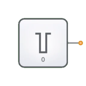
- Symbol: Typically represented as a small block with "0" indicated inside and a single output line.
- DigiSim.io Role: Provides a reliable ground or logic-low reference signal for various digital circuit applications where a fixed LOW value is needed.
Functional Description
Logic Behavior
The Constant Zero component continuously outputs a LOW (logical '0') signal, regardless of any other conditions in the circuit.
Truth Table:
| Output |
|---|
| 0 |
Inputs and Outputs
- Inputs: None. The component has no inputs as it is a signal source.
- Output: A single 1-bit output that is permanently set to LOW (logical '0').
Configurable Parameters
- None. The Constant Zero component has no configurable parameters as its behavior is fixed by definition.
Visual Representation in DigiSim.io
The Constant Zero is displayed as a small block with "0" indicated inside and a single output pin on the right side. When connected in a circuit, the component visually indicates its fixed LOW state through color changes on connecting wires.
Educational Value
Key Concepts
- Signal Sources: Demonstrates the concept of fixed signal sources in digital systems.
- Logic Levels: Reinforces understanding of binary logic states and the role of the LOW (0) state.
- Reference Signals: Illustrates how reference signals are used in digital design.
- Digital Abstraction: Shows how physical concepts like "ground" are represented in logical circuit design.
- Circuit Initialization: Introduces the concept of providing initial or default values to digital systems.
Learning Objectives
- Understand the role of constant signals in digital circuit design.
- Learn how to properly tie unused inputs to a defined level to prevent floating inputs.
- Recognize where ground references are needed in logical circuits.
- Apply the Constant Zero component to disable features or set default states.
- Comprehend the importance of defined logic levels in digital systems.
Usage Examples/Scenarios
- Pull-Down References: Providing a stable LOW reference for pull-down functionality.
- Input Termination: Tying unused inputs to a defined logic level to prevent floating inputs.
- Feature Disabling: Permanently disabling certain features or functions in configurable circuits.
- Default Conditions: Setting default "false" conditions in logical operations.
- Multiplexer Control: Providing fixed channel selection signals to multiplexers or decoders.
- Testing and Debugging: Creating known input conditions for verifying circuit behavior.
Technical Notes
- The Constant Zero component has no propagation delay as it does not process any inputs.
- In physical implementations, Constant Zero signals are typically provided by direct connections to ground (GND).
- Using Constant Zero is more reliable than leaving inputs unconnected, as unconnected inputs can lead to unpredictable behavior.
- In DigiSim.io, the Constant Zero component ensures that its connected points are always at a defined LOW logic level.
- Unlike a switch that could be toggled, the Constant Zero provides an immutable logic level that cannot be changed during simulation.
Characteristics
- Provides a steady, unchanging LOW (0) logic level
- No inputs - requires no control signals
- Single output that is always LOW (0)
- Cannot be modified during circuit operation
- Useful as a permanent ground reference signal
- Has no propagation delay (the output is always available)
- Often represented as a connection to ground in schematic diagrams
Applications
- Pull-down signals in digital circuits
- Disabling or permanently deactivating certain features
- Setting fixed control lines in multiplexers and decoders
- Providing "always false" conditions in logical operations
- Creating ground reference levels in digital systems
- Serving as a known input for testing and debugging
- Initializing sequential circuits to known states
- Tying unused inputs to a defined level to prevent floating inputs
Implementation
In real hardware implementations, constant zero signals are provided by:
- Direct connections to ground (GND)
- Hard-wired logic levels in digital ICs
- Programmed constant values in programmable logic devices
Related Components
- Constant: Provides a permanent HIGH (1) signal instead of LOW (0)
- Input Switch: Provides a user-controllable signal that can be toggled
- Clock: Provides a regularly alternating signal instead of a constant value
- Ground: Physical equivalent in electronic circuits