Decoder
Overview
- Purpose: The Decoder is a combinational logic circuit that converts a binary code input into a set of individual output lines, where only one output is active for each unique input code. It expands a compact binary representation into a "one-hot" format.
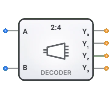
- Symbol: The Decoder in DigiSim.io is a 2-to-4 decoder represented by a rectangular block with 2 binary input lines (A0, A1) and 4 output lines (Y0, Y1, Y2, Y3).
- DigiSim.io Role: Serves as a fundamental building block for address decoding, data routing, and control signal generation in digital circuits.
Functional Description
Logic Behavior
The Decoder activates exactly one output line based on the binary value present at its inputs. Only the output corresponding to the binary input combination goes HIGH; all other outputs remain LOW.
Truth Table (2-to-4 Decoder):
| A1 | A0 | Y0 | Y1 | Y2 | Y3 |
|---|---|---|---|---|---|
| 0 | 0 | 1 | 0 | 0 | 0 |
| 0 | 1 | 0 | 1 | 0 | 0 |
| 1 | 0 | 0 | 0 | 1 | 0 |
| 1 | 1 | 0 | 0 | 0 | 1 |
Inputs and Outputs
Inputs:
- Address Inputs (A0, A1): 2 binary inputs that determine which output will be activated.
Outputs:
- Output Lines (Y0-Y3): 4 output lines, where only one output is active (HIGH) for each unique input combination.
Configurable Parameters
- Active Level: Whether outputs are active-high (1) or active-low (0).
- Propagation Delay: The time it takes for outputs to change after input changes.
Visual Representation in DigiSim.io
The Decoder is displayed as a rectangular block with 2 input pins (A0, A1) on the left or bottom side and 4 output pins (Y0-Y3) on the right or top side. It is labeled with a "2:4" size designation. When connected in a circuit, the component visually indicates which output is active through color changes on connecting wires.
Educational Value
Key Concepts
- Binary Encoding/Decoding: Demonstrates how binary values can be expanded into one-hot representations.
- Address Selection: Illustrates how binary addresses are used to select specific memory locations or devices.
- One-Hot Encoding: Introduces the concept of having exactly one active signal among many possible signals.
- Combinational Logic Design: Shows how complex functions can be implemented with basic logic elements.
Learning Objectives
- Understand how binary values are decoded into individual selection lines.
- Learn how decoders enable efficient addressing in digital systems.
- Recognize the role of decoders in memory systems and control units.
- Apply decoders in designing address decoding circuits and control signal generators.
- Comprehend how decoders can be cascaded to create larger decoding structures.
Usage Examples/Scenarios
- Memory Addressing: Selecting specific memory chips or memory locations based on address bits.
- Instruction Decoding: Generating control signals based on instruction opcodes in processors.
- Input/Output Selection: Activating specific peripheral devices based on address values.
- Display Driving: Converting binary values to segment patterns in display systems.
- State Decoding: Generating specific control signals based on the current state in state machines.
Technical Notes
- The DigiSim.io decoder is a 2-to-4 decoder with 2 inputs (A0, A1) and 4 outputs (Y0-Y3).
- The relationship between the number of inputs (n) and outputs (m) in a decoder is typically m = 2^n.
- Decoders can be cascaded to create larger decoders. For example, two 2-to-4 decoders with an additional input can create a 3-to-8 decoder.
- In active-low decoders, outputs are normally HIGH and go LOW when selected, which is often used in memory chip select applications.
- In DigiSim.io, decoders respond immediately to input changes, modeling the combinational logic behavior of these components.
Types of Decoders
Binary Decoders
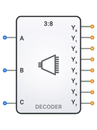
- Standard n-to-2ⁿ decoders (e.g., 2-to-4, 3-to-8, 4-to-16)
- Convert binary code to one-hot output
BCD-to-Decimal Decoders
- 4-to-10 decoders converting BCD to decimal display
- Common in display applications
Address Decoders
- Used for memory and I/O address selection
- Often include chip select outputs
Seven-Segment Display Decoders
- Convert binary/BCD inputs to seven-segment display outputs
- 4-to-7 decoders for numeric displays
Demultiplexers
- Special case of decoders used for data routing
- Route one input to one of several outputs
Active-Low Decoders
- Outputs are normally high, active outputs go low
- Often used in memory systems
Applications
Memory Address Decoding
- Selecting the correct memory chip or memory location
- Chip select generation in memory systems
Instruction Decoding
- Generating control signals in CPUs
- Opcode interpretation
Data Routing
- Directing data to appropriate processing units
- Bus addressing in microprocessors
Display Systems
- Driving seven-segment displays
- LCD/LED matrix control
Keyboard/Keypad Scanning
- Scanning matrix keyboards
- Input device control
Demultiplexing Operations
- Signal routing in communication systems
- Channel selection
Control Signal Generation
- Generating specific control signals based on instruction codes
- State machine outputs
Implementation Methods
Logic Gate Arrays
- AND gates with input inverters as needed
- Often arranged in a tree structure
Integrated Circuits
- 74LS138: 3-to-8 decoder
- 74LS154: 4-to-16 decoder
- 74LS47: BCD to 7-segment decoder
NAND/NOR Gate Implementation
- Using universal gates for all decoder functions
- Typically requires fewer gates than AND/OR
HDL Design
- Using case statements or conditional assignments
- Easily parameterized for different sizes
ROM-Based Implementation
- Using look-up tables for complex decoder functions
- Programmable logic approaches
Circuit Implementation (2:4 Decoder)
A simple 2-to-4 decoder can be implemented using AND gates with inverters:
graph LR
    InputA0[A0] --> NotGate0[NOT]
    InputA1[A1] --> NotGate1[NOT]

    NotGate0 --> AndGate0[AND]
    NotGate1 --> AndGate0
    AndGate0 --> OutputY0[Y0: 00]

    InputA0 --> AndGate1[AND]
    NotGate1 --> AndGate1
    AndGate1 --> OutputY1[Y1: 01]

    NotGate0 --> AndGate2[AND]
    InputA1 --> AndGate2
    AndGate2 --> OutputY2[Y2: 10]

    InputA0 --> AndGate3[AND]
    InputA1 --> AndGate3
    AndGate3 --> OutputY3[Y3: 11]
Output Selection: Each output corresponds to a unique 2-bit address combination.
Boolean Equations (2:4 Decoder)
For a 2-to-4 decoder:
- Y0 = Ā1 · Ā0
- Y1 = Ā1 · A0
- Y2 = A1 · Ā0
- Y3 = A1 · A0
Where · represents logical AND and Ā represents logical NOT
Related Components
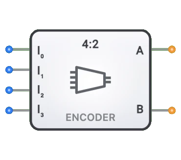
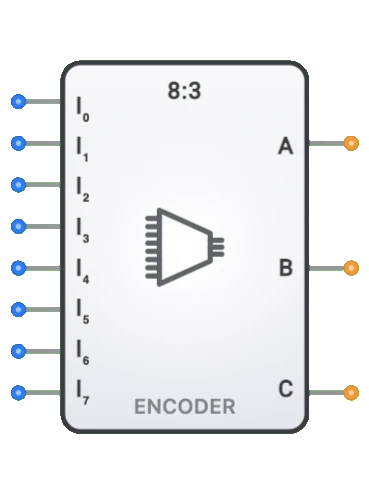
- Encoders: Perform the inverse operation (one-hot to binary)
- Multiplexers: Select one of many inputs based on select lines
- Demultiplexers: Functionally similar but route data rather than generate patterns
- Priority Encoders: Special encoders that handle multiple active inputs
- Display Drivers: Often contain decoders for display control
- Memory Address Decoders: Specialized for memory systems
- Programmable Logic Arrays: Can implement decoder functions