Input Switch
Overview
- Purpose: The Input Switch is a digital component that allows manual control of a binary signal value. It converts a user's action into a logical HIGH or LOW signal, providing interactive input to digital circuits.
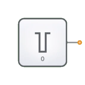
- Symbol: The Input Switch is represented by a toggle switch symbol with an output pin.
- DigiSim.io Role: Provides a user-controlled input mechanism for digital circuits in the simulation environment, enabling interactive testing and demonstration of circuit behavior.

Functional Description
Logic Behavior
The Input Switch outputs a constant binary value that can be manually toggled between HIGH and LOW states by the user.
States:
| Switch State | Output Value |
|---|---|
| OFF position | 0 (LOW) |
| ON position | 1 (HIGH) |
Inputs and Outputs
- Inputs: None. The Input Switch is controlled directly by user interaction rather than by logical inputs.
- Output: A single 1-bit output providing either a HIGH or LOW signal based on the switch position.
Configurable Parameters
- Initial State: The starting position of the switch (ON or OFF).
- Label: Optional text label that can be assigned to identify the switch's purpose in the circuit.
Visual Representation in DigiSim.io
The Input Switch is displayed as a toggle switch that can be clicked to change its state. When in the ON position, the switch and its output wire visually indicate a HIGH state through color changes. When in the OFF position, they indicate a LOW state. The graphical representation makes it clear which position the switch is currently in.
Educational Value
Key Concepts
- Signal Generation: Demonstrates the concept of binary signal sources in digital systems.
- User Interface: Illustrates how human input can be translated into digital signals.
- Control Flow: Shows how input signals determine circuit behavior.
- State Control: Introduces manual state setting in digital circuits.
Learning Objectives
- Understand how binary inputs affect digital circuit operation.
- Learn to use switches to test and verify circuit functionality.
- Recognize the role of user inputs in digital system design.
- Apply input switches correctly to create interactive digital systems.
- Develop skills in circuit debugging using controlled inputs.
Usage Examples/Scenarios
- Logic Testing: Verifying the behavior of logic gates and combinational circuits.
- Initial Condition Setting: Establishing starting states for sequential circuits.
- Mode Selection: Enabling or disabling specific functions in a digital system.
- Manual Data Entry: Inputting binary data values for processing.
- Control Signals: Providing control signals for components like multiplexers, decoders, or enable lines.
Technical Notes
- Unlike the Clock component, which generates periodic signals automatically, the Input Switch maintains its state until manually changed.
- Multiple Input Switches can be combined to create multi-bit inputs for binary values.
- In DigiSim.io, switches respond immediately when toggled, whereas physical switches may require debouncing circuits.
- The Input Switch can be used to isolate and debug specific parts of a circuit by controlling input conditions precisely.
Implementation
In real-world applications, input switches are implemented using:
- Mechanical toggle or push-button switches with debouncing circuits
- DIP (Dual In-line Package) switches for configuration settings
- Touchscreen or keyboard inputs in software simulations
- Relay contacts in some industrial applications
Related Components
- Clock: Provides an automated alternating signal, unlike the manually set Input Switch
- Constant: Provides a fixed value (0 or 1) without manual intervention
- Button: A momentary version of a switch that returns to its default state when released