Flags Register
Overview
- Purpose: The Flags Register is a special-purpose register that stores status bits (flags) reflecting the outcome of arithmetic or logical operations. Each bit corresponds to a specific condition, such as whether a result was zero, negative, produced a carry, or caused an overflow.
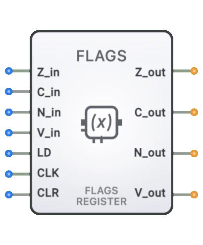
- Symbol: Represented as a rectangular register block with 7 inputs (4 flag data bus inputs + CLK + LD + flag input) and 4 flag outputs (Z, C, N, V).
- DigiSim.io Role: Serves as a crucial component in computer architecture simulation, enabling conditional operation and decision-making based on the results of previous calculations.
Functional Description
Logic Behavior
The Flags Register captures and stores status information generated by the ALU or other computational units. Each bit in the register represents a specific condition or state.
Flags:
| Flag | Set Condition | Clear Condition |
|---|---|---|
| Zero (Z) | Result of operation is zero | Result is non-zero |
| Carry (C) | Unsigned addition overflow / Subtraction borrow | No unsigned overflow / No borrow |
| Negative (N) | Most significant bit (MSB) of result is 1 | MSB of result is 0 |
| Overflow (V) | Signed arithmetic operation overflowed | No signed overflow |
Inputs and Outputs
Inputs (7 total):
- Zero (Z): Pin 0. Zero flag input from ALU (bus input).
- Carry (C): Pin 1. Carry flag input from ALU (bus input).
- Negative (N): Pin 2. Negative flag input from ALU (bus input).
- Overflow (V): Pin 3. Overflow flag input from ALU (bus input).
- Flag In: Pin 4. Additional flag input (bus input).
- CLK: Pin 5. Clock input — flags are captured on the rising edge.
- LD (Load): Pin 6. Load enable — flags are updated only when LD is HIGH on the rising clock edge.
Outputs (4 total):
- Z: Pin 0. Zero flag output.
- C: Pin 1. Carry flag output.
- N: Pin 2. Negative flag output.
- V: Pin 3. Overflow flag output.
Configurable Parameters
- Included Flags: Which specific status flags are implemented (architecture dependent).
- Flag Behavior: How each flag responds to specific operations.
- Clock Edge Sensitivity: Whether the register updates on rising or falling clock edges.
- Load Control: Whether flags update individually or as a group.
- Propagation Delay: The time it takes for flag outputs to reflect input changes.
Visual Representation in DigiSim.io
The Flags Register is displayed as a rectangular block with labeled inputs on the left side (Status bits, CLK, Load) and individual flag outputs on the right side (Z, C, N, V, etc.). When connected in a circuit, the component visually indicates the state of each flag through output values and color changes on connecting wires.
Educational Value
Key Concepts
- Conditional Execution: Demonstrates how computers make decisions based on operation results.
- Status Tracking: Shows how digital systems keep track of computation outcomes.
- Computer Architecture: Illustrates a fundamental component of CPU design.
- State Information: Introduces the concept of maintaining state information for use in subsequent operations.
- Digital Feedback: Shows how the results of operations influence future processing paths.
Learning Objectives
- Understand how status flags capture the outcomes of arithmetic and logical operations.
- Learn how flags enable conditional branching and decision-making in computer programs.
- Recognize the role of the Flags Register in CPU architecture and instruction execution.
- Apply knowledge of flags to predict program flow in conditional operations.
- Comprehend how multi-precision arithmetic relies on carry and overflow flags.
Usage Examples/Scenarios
- Conditional Branching: Jump if Zero (JZ), Jump if Carry (JC), or Jump if Not Zero (JNZ) instructions use flags to alter program flow.
- Multi-precision Arithmetic: Using the Carry flag to link operations across multiple words (e.g., adding 64-bit numbers on a 32-bit ALU).
- Error Detection: Monitoring the Overflow flag to detect arithmetic errors in signed operations.
- Loop Control: Checking the Zero flag to determine when loop counters reach terminal values.
- Interrupt Management: Setting or clearing the Interrupt flag to control system responsiveness to external events.
- Status Reporting: Using flags to communicate operation outcomes to higher-level software.
Technical Notes
- The Flags Register is typically implemented as a collection of flip-flops, one for each flag bit.
- Different CPU architectures include different sets of flags and may interpret them differently.
- Flag behavior can vary by instruction; some instructions may affect all flags, while others affect only specific flags.
- In many CPU designs, the Flags Register is part of a larger Program Status Word (PSW) or Status Register.
- Saving and restoring the Flags Register is often necessary during context switches, interrupts, and subroutine calls.
- In DigiSim.io, the Flags Register behavior models common CPU architectures with proper flag setting and clearing based on input conditions.